Vermont Casting BREF30 User Manual
Page 8
10004758
BREF Electric Fireplace
8
120 Volt Unit Installation
1. Locate the switch under the logset on the left front
corner of the unit.
2. Check the voltage selection switch position to ensure
it is in the 120 Volt position.
3. Loosen the screws securing the junction box cover
and remove the cover.
4. Remove knockouts in the box cover to use the cable
clamp.
5. Pull out two (2) wires: black and white.
6. Connect the black wire from the unit to the L1 (black)
from the power supply. Connect the white wire from
the unit to the neutral (white) from the power supply.
NOTE: Wiring must be connected to a 20 Amp
dedicated circuit breaker or fuse in the electrical
panel of the dwelling.
7. Connect the ground wire from the power supply to
ground stud in the junction box.
8. Make sure the red wire (L2) in the junction box has a
closed end splice or a wire nut properly applied.
9. When the unit has been configured for the appropri-
ate power supply voltage, ensure all connections
are tight. Insert all wiring inside the junction box and
secure the cover.
10. Turn the power to the unit on at the breaker/fuse
panel. Place the unit into operation and check to
make sure the whole system is operating properly.
120 Volt (NH) Unit Installation
1. Loosen the screws securing the junction box cover
and remove the cover.
2. Remove knockouts in the box cover to use the cable
clamp.
3. Pull out two (2) wires: black and white.
4. Connect the black wire from the unit to the L1 (black)
from the power supply. Connect the white wire form
the unit to the neutral (white) form the power supply.
5. Connect the ground wire from the power supply to
the ground stud in the junction box.
6. Ensure all connections are tight. Insert all wiring
inside the junction box and secure the cover.
7. Turn the power to the unit on at the breaker/fuse
panel. Place the unit into operation and check to
make sure the system is operating properly.
240 Volt Unit Installation
1. Locate the voltage selection switch under the logset
on the left front corner of the unit.
2. Check the switch position to ensure it is in the
240 Volt position.
3. Loosen the screws securing the junction box cover
and remove the cover.
4. Remove knockouts in the box cover to use the cable
clamp.
Resetting the
Temperature Cutout Switch
To reduce the risk of fire, electrical shock,
and personal injury, before attempting
maintenance or service, disconnect all
power to the fireplace at the main service
panel.
NOTE: The heater on this fireplace is protected with
a safety limit device to prevent overheating. Should
the heater overheat, an automatic cutout turns the
heater OFF; it will not come back ON without being
manually reset.
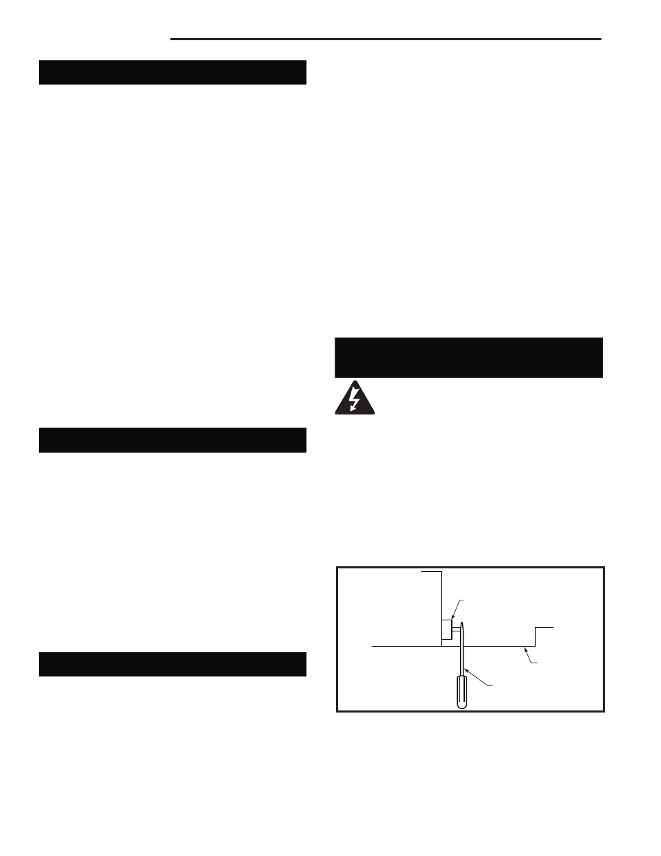
The safety limit device is located in a cutout at the right
front top corner by the cover fan/ heater. To reset the
switch, insert a small flat screwdriver into this cutout
and push the reset button on the safety limit device.
5. Pull out three (3) wires: black, red, and white.
6. The unit is shipped from factory with a closed end
splice on the red wire. Cut off this splice and strip
approximately 5/8" (15mm) wire sheathing.
7. Connect the black wire from the unit to the L1
(black) from the power supply. Connect the red wire
from the unit to the L2 (red) from the power supply.
Connect the white wire from the unit to the neutral
(white) from the power supply.
NOTE: Wiring must be connected to a 20 Amp
dedicated circuit breaker or fuse in the electrical
panel of the dwelling.
8. Connect the ground wire from the power supply to
ground stud in the junction box.
9. When the unit has been configured for the appropri-
ate power supply voltage, ensure all connections
are tight. Insert all wiring inside the junction box and
secure the cover.
10. Turn the power to the unit on at the breaker/fuse
panel. Place the unit into operation and check to
make sure the whole system is operating properly.
FP1452
Safety limit switch
2/25/04 djt
Safety Limit Device
Small Flat Screwdriver
Cover Fan/
Heater
FP1452
Fig. 4 Reset the switch with a small flat screwdriver.