Bref electric fireplace, Fp1450 bref wiring diagram w/remote – Vermont Casting BREF30 User Manual
Page 12
10004758
BREF Electric Fireplace
12
FAN/HEATER
MOTOR
FLAME
MOTOR
L2
L1
N
11 RED
22 WHITE
12 BLACK
T'S
WHITE
18 WHITE
G
1 WHITE
BLACK
BLACK
17 WHITE
7 BLACK
6 RED
13 RED
16 BLACK
9 BLACK
14 BROWN
8 BLACK
2 WHITE
WHITE
23 WHITE
19 WHITE
24 WHITE
21 WHITE
4 BLACK
5 BLACK
1
2
3
4
5
6
COIL
16 BLACK
15 BLACK
REAR
FRONT
14 BROWN
1a
1
1b
2a
2
2b
25 RED
IN
IN
OUT
OUT
L
N
N
L
12
13
13
5
4
2
3
15
1
9
11
10
16
7
8
20 WHITE
10 BLACK
3 BLACK
4 BLACK
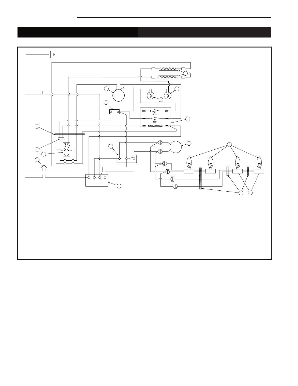
FP1450
BREF wiring diagram
w/remote
6
Electrical Wiring Diagram with Integral Remote Control
For Units with Ceramic Log Sets (Refer to Figures 6 & 7)
Component Identification
1. Heater Element
9. Light Bulb
2. Limit Control, 175/20 DIF
10. Light Socket w/Wiring Assembly
3. Relay Switch, 120V, 50/60Hz
11. Cable Tie Nylon 6"-1¹⁄₂" Black
4. Fan/Heater Motor
12. Bushing Snap, Split 1"
5. Thermostat
13. Closed End Splice 2/18 Ga.Wire
6. Switch, Rocker
14. CFM Wire
7. Switch
15. Sensor, 230°F Manual Reset
8. Flame Motor
16. Receiver
FP1450
Fig. 9 Wiring Diagram for units with ceramic log set. (Refer to Figures 6 & 7) BREF36R/BREF42R