GME GD9640B User Manual
Page 8
PA G E 8
i n s t r u c t i o n m A n uA l
G D 9 6 0 0 s E r i E s
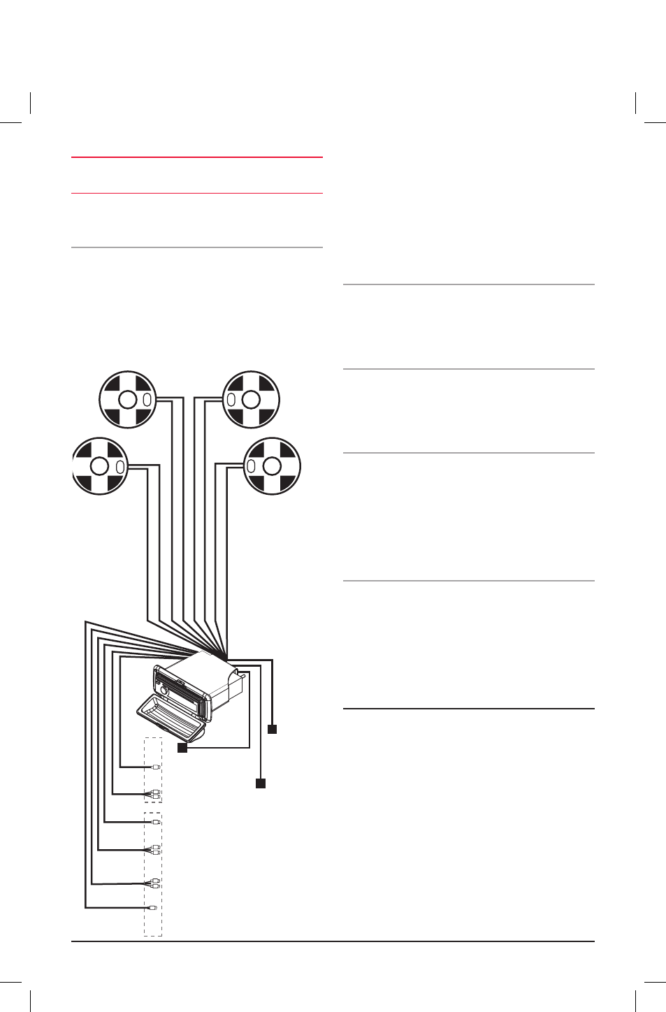
caution:
the gd9600 is a four-speaker system that
requires 2 separate wires for each speaker.
A range of GmE speakers are available from your local
GmE retailer.
speaker connections
When connecting the speakers, observe the correct polarity
as shown in the diagram below. incorrect polarity will result
in a reduction of bass response and stereo effect. the use
of speakers with an impendance of less than 4 ohms is not
recommended, as they will cause excessive loading of the
GD9600’s output circuit and may result with the
radio overheating.
connect all four speakers as shown in the previous diagram.
Adjust the Fader control for the required front/rear balance.
if you wish to connect only two speakers, connect these to
the rear speaker wires. the remaining speaker wires should
be insulated to ensure they cannot short circuit together or
to the vessel’s 12 Volt or negative electrical Bus. if using only
two speakers, adjust the Fader control to the rear speakers.
antenna connections
connect an Am/Fm marine antenna to the antenna
socket which extends from the rear of the GD9600. For
information on a suitable antenna, contact your nearest
GmE branch or marine retailer.
Wired remote control
the GD9600 has 1 additional fly lead at the rear enabling
a GmE wired remote (rcu9200) to be connected. one or
more additional 5 meter leads (lEo24) can also be inserted
if required up to a maximum of 15 meters.
ipod® connectivity
the GD9600 has a 2nd fly lead which, when connected with
an lEo23 (optional 1.1 meter lead), enables an iPod® to
be connected directly to the stereo. limited functions of the
iPod® can be accessed via the GD9600, including the
selection of albums and songs. Access to displaying the
iPod® library on the GD9600 is not available however the
iPod library and all functions can be viewed on the iPod.
reset Button
When the installation is complete, press the reset
button on th face using a paper clip or similar object (see
‘instAllAtion PrEcAutions’ on page 4). this will ensure
the GD9600 is ready to operate for the first time. if at any
time the controls do not seem to work (after replacing the
vessel’s battery for example), press the reset button to
reset the microcomputer inside the GD9600.
fuse replacemeNt
if any of the fuses blow, replace them with a standard
30 mm 3 AG type of the same rating, if the fuse blows a
second time contact your retailer.
the following fuse ratings are used:
-Yellow ‘memory 12 V +’ lead: 15 Amp.
-red ‘ignition switch Acc’ lead: 0.5 Amp.
REAR LEFT - GREEN/BLA
CK
REAR LEFT + GREEN
FRONT LEFT -
WHITE/BLA
CK
FRONT LEFT +
WHITE
FRONT RIGHT + GREY
REAR RIGHT + PURPLE
REAR RIGHT - PURPLE/BLA
CK
WIRED REMOTE
CONNECTION
iPOD INPUT
VIA OPTIONAL LEAD
BROWN
Left Front
Left Rear
+
-
-
-
-
+
+
+
Right Front
Right Rear
YELLOW: VIDEO IN
RED: AUDIO IN R
WHITE: AUDIO IN L
RED: AUDIO OUT REAR R
WHITE: AUDIO OUT REAR L
RED: AUDIO OUT FRONT R
WHITE: AUDIO OUT FRONT L
YELLOW: VIDEO OUT
BLACK: DIGITAL COAXIAL AUDIO OUT
ANTENNA CONNECTOR
DVD
OUT
AUX2
IN
BLACK
BLA
CK
WHITE
BLACK
BROWN
BLACK
GREY
FRONT RIGHT - GREY/BLA
CK