Connection led display, Set up – Futaba MC401CR User Manual
Page 2
N
N
N
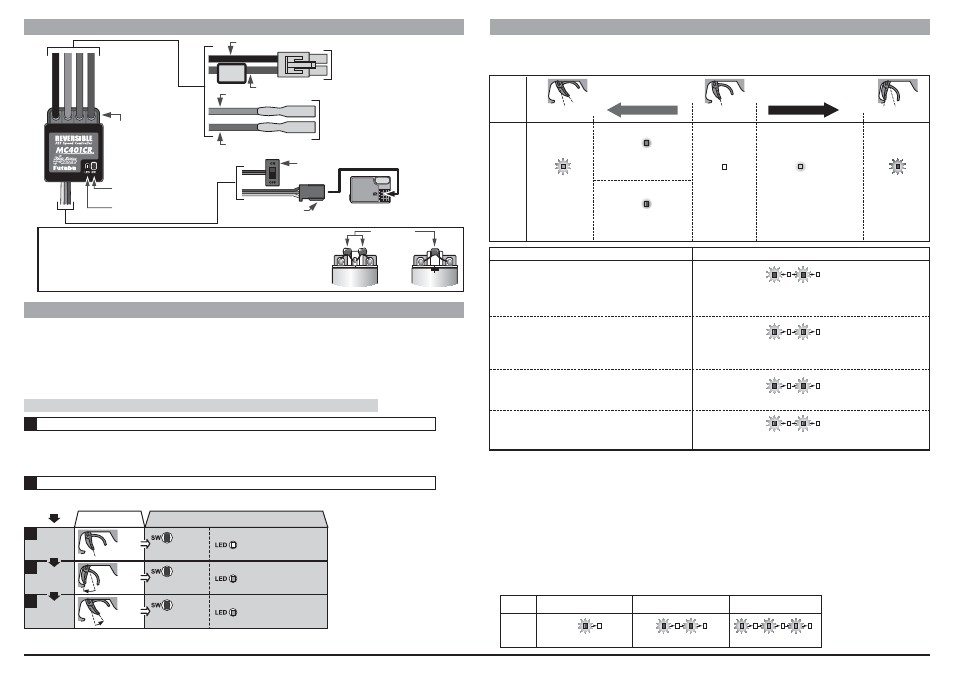
CONNECTION
LED DISPLAY
In set-up mode MC401CR stores every step when you press the Set-up button. All the settings are stored in the unit even when the
speed control is subsequently disconnected from the battery. Set up the following basic functions on your transmitter (if present):
s
)F
2EMOVE
s Switch the transmitter on.
s
*
$EPENDING
(Alarm: Waiting for neutral data)
Turn on the power in following order.
s
s
Hold the SET button pressed in for at least 3 seconds using the small screwdriver supplied.
©FUTABA CORPORATION
2007,11
MC401CR
Protection Circuits
Heat protection:
!FTER
A
7HEN
RECEIVER
Reverse Cancelling function (Brake operation only)
7HILE
7HEN
The reverse mode by LED can check.
3ET
SET button operation
LED
Neutral
point
setting
High
point
setting
Brake MAX
point
setting
s Neutral state
s
ONCE
flashes red and the motor beeps.
*Not used with PCM receivers.
*When the transmitter if OFF, this function is not performed in environments such
that the servo operates erroneously
On (red)
High
point
On (green)
Brake MAX
point
Brake or Reverse
Brake
Reverse
On (red)
*Becomes brighter nearer the
MAX point.
On (orange)
*Becomes brighter nearer the
MAX point.
Foward
On (green)
*Becomes brighter nearer the high
point.
LED
LED
LED
MODE
SET UP
s Full brake
state
s Full high
state
s Press SET button
once.
s Press SET button
once.
s Press SET button
once.
LED goes out
and the
motor beeps.
flashes green two times
and the motor beeps.
LED goes out
flashes orange and the motor beeps.
flashes orange
flashes red and the motor beeps.
flashes green three times
and the motor beeps.
LED goes out
* Since the data is read at the end of setting
of all points, the points cannot be set
independently.
* If the amp power was turned off during
setting, the setting points cannot be
memorized. (The previous settings are
retained.)
* The confirmation beep sounds only when
the motor was connected.
* If you make a mistake during the set-up
procedure, an setting is not completed.:
switch MC401CR off and start again from
the first step.
* Check the operation by the following "LED
DISPLAY." When throttle operation and
the CHECKER LED DISPLAY are not
correct, set up again from the first step.
(Amp power left on alarm)
When the transmitter power
was turned off first.
Off
Neutral
point
*at Neutral Brake:
On (green or red)
*When the switch of speed control is turned ON ahead of a
transmitter.
*When the neutral position of a transmitter differs from the last setup.
(Alarm when waiting for the data of a neutral point)
Operation
Cause
(Protection circuit operation)
When a protection circuit operates.
(Data error alarm)
Displayed when an abnormal signal was input.
Transmitter throttle
operation
3
4
5
1
2
&54!"!
Silicone flex wire Orange
Silicone flex wire Red
Silicone flex wire Blue
Silicone flex wireBlack
Fuse
Motor connector
Connects to the motor.
(Orange) is plus. (Blue) is minus.
If the motor rotates in the wrong direction,
interchange the connections of this connector.
Nicd battery connector
Connects to the running Nicd battery.
(Red) is plus. (Black) is minus.
Receiver connector
Connects to the receiver throttle channel (CH2).
Power switch
Pushbutton switch
LED
Terminal cover
-OTORS
*
#AUTION
such as the MC401CR.
Solder the suppressor capacitors and the Schottky diode to the motor.
Suppressor
capacitors
The mode to reverse
The mode to cancel reverse
The mode to robot
flashes red twice
flashes green 3 times
flashes orange once