Utput, Able, Onnection – Flintec KPB-4 User Manual
Page 4: Orner, Orrection at, Cales with, Lintec, Ells
Junction Box Type KPB-4 – Technical Manual, Rev. 1.00 September 2007
Page 4 of 4
O
UTPUT
C
ABLE
C
ONNECTION
The signal cable (connection between junction box and the following electronics) should be a 6 – wire
shielded cable and has to be kept as short as possible. It will be pulled through a cable inlet which has to be
prepared at site.
Then feed the tin-plated wires through the hole at the solder point. Use a suitable soldering iron for electronic
works (at least 30 Watt ). Proper solder joints always look bright and shiny.
Never use soldering solution and soldering grease! This will destroy the printed circuit board!
Always use suitable electronic solder, e.g. S-Sn60Pb40 DIN EN 29453.
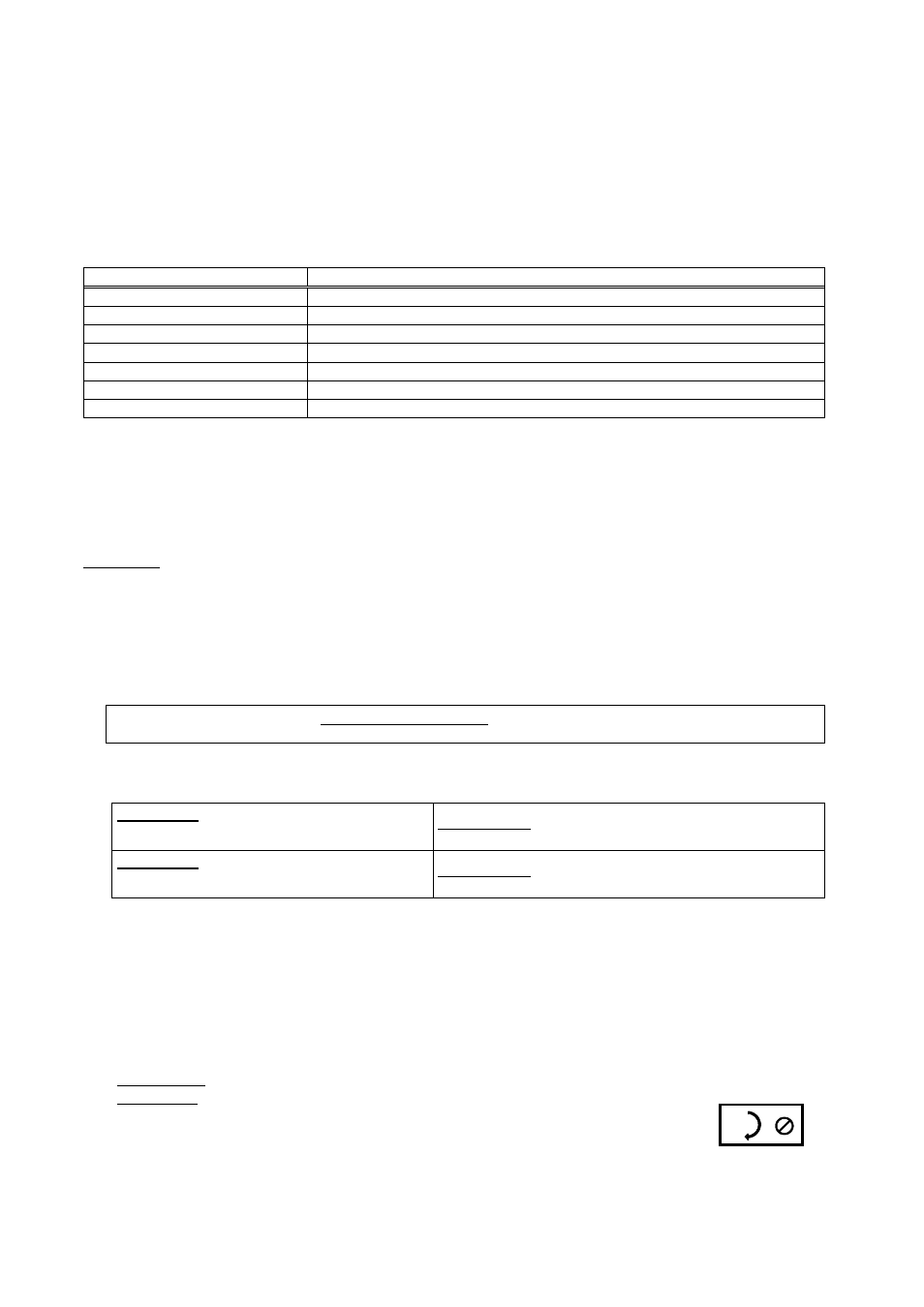
Depending on type and manufacturer signal cables may have different colours. Therefore make your own
choice.
Cable colour, example
Description / Terminal designation
outer cable screen
= Shield
pink
= Out – (Signal –)
white
= Out + (Signal +)
grey
= Sense –
brown
= In – (Excitation –)
yellow
= Sense +
green
= In + (Excitation +)
C
ORNER
C
ORRECTION AT
S
CALES WITH
F
LINTEC
L
OAD
C
ELLS
Flintec load cells are manufactured with rather tight tolerances, so in most cases an additional corner
correction is not required. The best conditions are achieved if you use load cells of the same class
(Designation is done with capital letters A to I on the load cell package besides the type label).
Hint: Corner errors can have a mechanical background, e.g. sloped mounting surface of the load cell.
Procedure:
1. The jumpers JP1 to JP4 besides the potentiometer should stay installed. This will disable the
potentiometers (shipment status).
2. Get the display value for each corner. Use the highest possible display resolution (e.g. factor 10 or higher)
or, if this is not possible, measure the the digital weight increment using corresponding weights.
3. The corner with the lowest display value is the starting point for the corner correction. The differences of
the other corners are calculated with reference to this “basic corner”.
4. Calculate the correction resistance as follows:
Deviation in [kg]
Correction resistance [Ω] =
Test load in [kg]
X Input resistance of the load cell [Ω] *
* 1100 Ω input resistance for:
BK2, SB4, SB5, SB6, SB14, SLB, ZLB, UB1, UB5, UB6, PB, RC3
400 Ω input resistance for:
RC1, SB2
Example 1: 1100 Ω load cell
0.1 kg corner error with 500 kg test load
0.1 kg
500 kg
x 1100 Ω
Ω
Ω
Ω =
0.22 Ω
Example 2: 400 Ω load cell
10 kg corner error with 5000 kg test load
10 kg
5000 kg
x 400 Ω
Ω
Ω
Ω =
0.8 Ω
5. The calculated correction resistance is used as the starting point when the correction is made with the
potentiometers P1 to P4 (25 turns; version 1: 10 Ohm Cermet- precision trimmer; version 2: 50 Ohm
trimmer). When shipped all potentiometers are in the middle position (appr. 5 Ohm) and disabled by the
jumpers JP1 to JP4 (short-circuit). If a potentiometer shall be enabled, the corresponding jumper JPx has
to be removed. First you have to turn the potentiometer to the clockwise end position (clicking noise).
Afterwards you turn the potentiometer counterclockwise until the computed correction resistance is
adjusted.
6. Check the corners again. If required repeat the procedure.
•
Use suitable screwdriver !
•
Version 1: One turn corresponds to appr. 0.4 Ohm
Version 2: One turn corresponds to appr. 2 Ohm
•
Clockwise end position = 0 Ohm
•
Version 1: Counterclockwise end position = 10 Ohm
Version 2: Counterclockwise end position = 50 Ohm
Hints for Poti
adjustment:
•
Jumpers besides the enabled potentiometers must stay removed
Finally install the cover of the box.