Flintec KPB-4 User Manual
Page 3
Junction Box Type KPB-4 – Technical Manual, Rev. 1.00 September 2007
Page 3 of 4
I
NTRODUCTION AND TECHNICAL
D
ATA
The plastic junction box is designed for the parallel connection of 4 load cells type PB or type PBW.
There are 2 versions available.
Type
No. of load cells
Housing size
Inputs Output
Vers.
Potentiom. Accuracy cl.
1
10 Ω
C3
KPB-4
up to 4x type PB/PBW 100 x 100 x 40 mm
4
1
2
50 Ω
GP
The junction box type KPB-4 can be connected to the instrumentation with a shielded 6-wire signal cable.
The corner correction is done with potentiometer.
Housing material:
Plastic
Protection class:
IP54
Cable connection:
Load cell cable with plug connector AMP #103957-4; output cable by soldering
Corner correction:
By potentiometer
M
ECHANICAL
I
NSTALLATION
Look for a mounting location which is more or less dry and protected from environmental stress.
Before you mount the junction box you should prepare (drill) a holl for the output cable.
E
LECTRICAL
C
ONNECTIONS
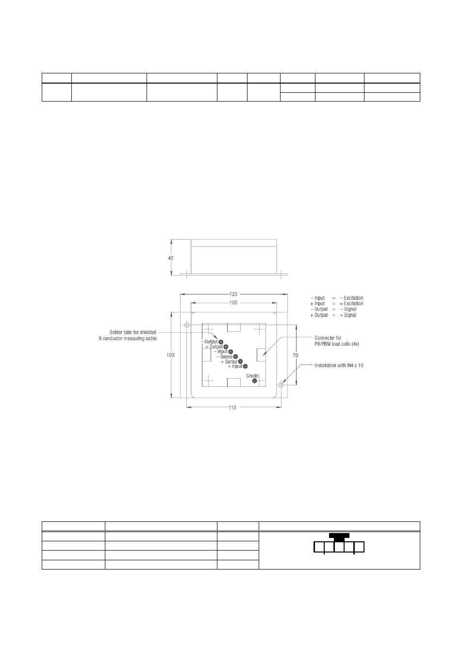
Figure 1: Dimensions in [mm]
The connection sequence of the load cells should correspond to the corners of the scale, i.e
Corner 1 = Load cell 1, Corner 2 = Load cell 2, etc.
L
OAD
C
ELL
C
ABLE
C
ONNECTION
Connect the load cell cable with its plug connector to the prepared plug connector on the printed circuit board.
Afterwards prepare the load cell cable with the delivered cable sleeve, so that later on the cable inlet gets tight
and the plug connector stress relieved.
The load cell cable connections at the AMP- plug are as follows:
Cable coulour
Description
Pin no.
Plug connector load cell cable (top view)
red
= Signal – (Output –)
5
white
= Signal + (Output +)
4
black
= Excitation – (Input –)
2
green
= Excitation + (Input +)
1
1 2 4 5
1 2 4 5
1 2 4 5
1 2 4 5