Dimensions and data – Flintec 52-05 User Manual
Page 4
www.flintec.com
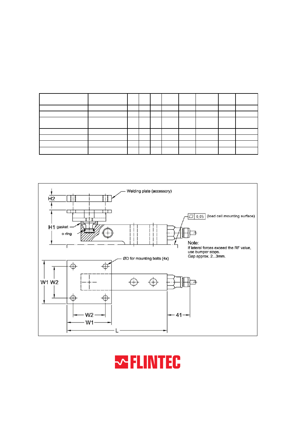
Dimensions and data
The table below shows maximum allowed lateral displacement for the
different capacities of rubber elements and the restoring force created by the
rubber at this displacement. The force is linearly proportional to the displacement.
If side forces exceeding RF are expected, external bumper stops must be
arranged.
* Including spacer.
** S
max
=maximum lateral displacement of load carrier.
*** RF =restoring force at S
max
.
All dimensions in mm. Dimensions and specifications are subject to change without notice.
CAD files for customer’s own applications drawings are available on request.
Load Cell Type
Capacity in kg
L
H1
H2
W1
W2
Mounting
bolts D
S
max
**
RF***
at S
max
SB4/SB5-5/10/20 kN
510/1020/2039
180
63
12
80
58
M8
5 mm
1600 N
SB4/SB5-50 kN
5099
219
78
15
100
76
M10
5 mm
5000 N
SB6-200 N/500N/
1 kN/2 kN
20.4/51/102/204
150 65*
10
60
44
M6
6 mm
700 N
SB14-500 lb
227
154
54
10
60
44
M6
6 mm
700 N
SB14-1/2.5/5 klb
454/1134/2268
164 60*
12
80
58
M8
5 mm
1600 N
SLB-200 lb/500 lb
91/227
154 55*
10
60
44
M6
6 mm
700 N
SLB-1/2.5/5 klb
454/1134/2268
164 59*
12
80
58
M8
5 mm
1600 N