Flintec 52-05 User Manual
Page 3
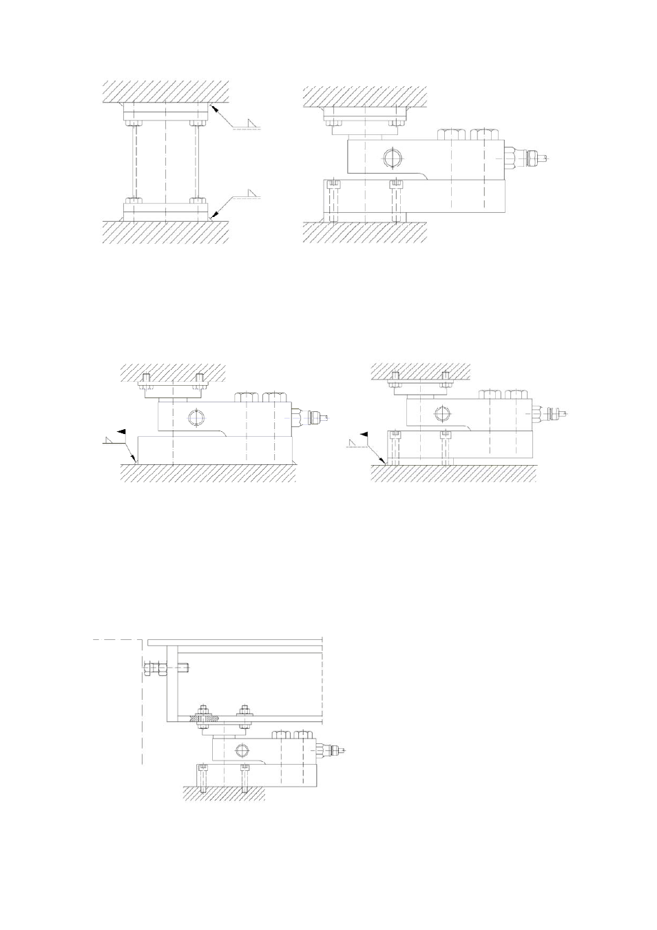
Figure 2.1
Figure 2.2
Welding plates can be accurately positioned in load carrier and foundation by
using Flintec welding fixtures (figure 2.1). After removal of fixture, the load cell,
base plate and rubber element can be installed (figure 2.2).
Figure 3.1
Figure 3.2
Examples where load cell is used as “welding fixture”. Base plate 52-00 welded
directly to foundation (figure 3.1). Make sure to ground welding machine in the
foundation plate. No current must flow through the load cell. Figure 3.2 shows the
same configuration but with a welding plate under the 52-00 base plate.
Figure 4
If big side forces, exceeding RF,
are expected, side movement
stops shall be arranged. For
example as shown in figure 4.