Operating instructions – ebm-papst A4D450-AO14-01 User Manual
Page 7
Operating instructions
A4D450-AO14-01
Translation of the original operating instructions
Connect the device only to circuits that can be switched off
using an all-pole disconnecting switch.
4.2.1 Prerequisites
; Check whether the data on the type plate agree with the connection
data.
; Before connecting the device, ensure that the supply voltage matches
the operating voltage of the device.
; Only use cables designed for current according to the type plate.
For determining the cross-section, follow the basic principles in
accordance with EN 61800-5-1. The protective earth must have a
cross-section equal to or greater than the outer conductor cross-
section.
We recommend the use of 105°C cables. Ensure that the minimum
cable cross-section is at least
AWG26/0.13 mm².
4.2.2 Residual current operated device
Only pulse-current sensitive and/or universal RCD protective
devices (Type A or B) are permitted. Like frequency inverters,
RCD protective devices cannot provide personal safety while
operating the device.
4.2.3 Voltage control
With open loop speed control using transformers or electronic
voltage regulators (e.g. phase angle control), excessive current
may occur.
In addition, noises can occur with phase angle control
depending on the mounting situation.
4.2.4 Frequency inverter
Please use a frequency converter only after consultation with ebm-papst.
When a frequency converter is used for speed adjustment, the
maximum safe operating speed (see 3.2 Nominal data) may not be
exceeded.
For operation with frequency converters, fit sinusoidal filters that
work on all poles (phase-phase and phase-earth) between the
frequency converter and the motor.
During operation with frequency converters, an all-pole sine
filter protects the motor against high-voltage transients that can
destroy the winding insulation system, and against harmful
bearing currents.
Heating of the motor due to use of a frequency converter must be
checked in the application by the customer.
4.3 Connection in terminal box
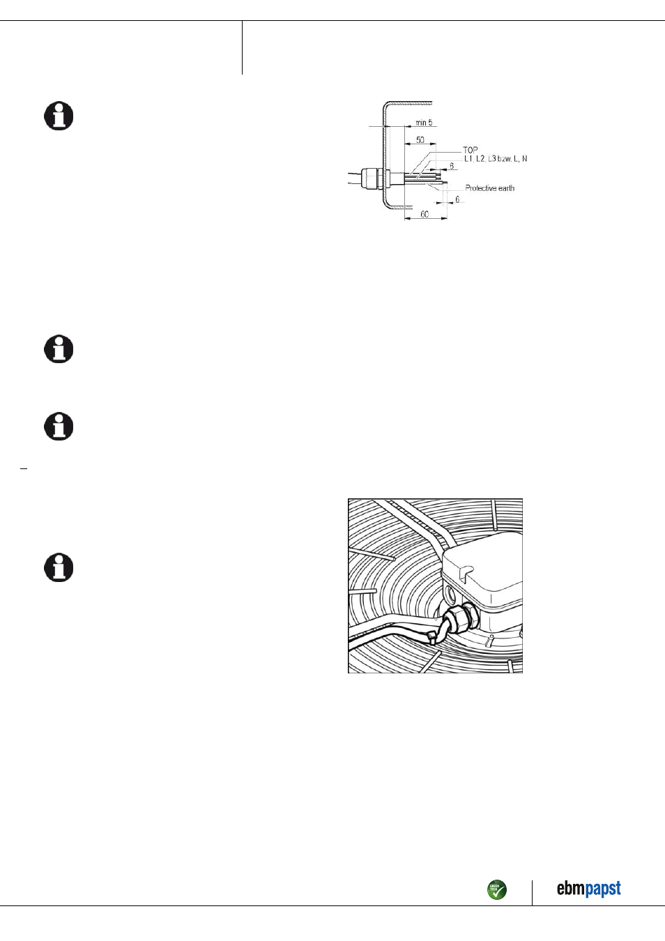
4.3.1 Preparing connection lines for the connection
Strip the cable just enough so that the screwed cable gland is tight and
the terminals are relieved of strain. Tightening torque, see chapter 3.1
Product drawing.
4.3.2 Connecting cables with terminals
; Remove the cap from the screwed cable gland.
Remove the cap only in those places where cables are inserted.
; Insert the line(s) (not included in the standard scope of delivery) into
the terminal box.
; First connect the "PE" (protective earth) connection.
; Connect the lines to the corresponding terminals.
; Connect the thermal overload protector (TOP).
Use a screwdriver to do so.
During the connection work, ensure that no cables splice off.
The terminal strip is equipped with a penetration prevention device.
; Insert the strands until they meet resistance.
; Seal the terminal box.
4.3.3 Cable routing
No water may penetrate along the cable in the direction of the cable gland.
Fans installed lying flat
Make sure that the cable is routed in the form of a loop (water trap).
Fig. 2: Fan installed lying flat, cable routed as a water trap.
Fans installed in upright position
When routing the cable, ensure that the screwed cable glands are
arranged at the bottom. The cables must always be routed downwards.
Item no. 11110-5-9970 · ENG · Revision 83823 · Release 2014-12-05 · Page 7 / 11
ebm-papst Mulfingen GmbH & Co. KG · Bachmühle 2 · D-74673 Mulfingen · Phone +49 (0) 7938 81-0 · Fax +49 (0) 7938 81-110 · [email protected] · www.ebmpapst.com