Operating instructions – ebm-papst M3G112-GA53-72 User Manual
Page 7
Operating instructions
M3G112-GA53-72
Translation of the original operating instructions
4.2.4 Locked-rotor protection
Due to the locked-rotor protection, the start-up current (LRA) is
equal to or less than the nominal current (FLA).
4.3 Connection in terminal box
4.3.1 Preparing connection lines for the connection
Strip the cable just enough so that the screwed cable gland is tight and
the terminals are relieved of strain. Tightening torque, see chapter 3.1
Product drawing.
4.3.2 Connecting cables with terminals
; Remove the cap from the screwed cable gland.
Remove the cap only in those places where cables are inserted.
; Mount the screwed cable glands with the seal inserts provided in the
terminal box.
; Insert the line(s) (not included in the standard scope of delivery) into
the terminal box.
; First connect the "PE" (protective earth) connection.
; Connect the lines to the corresponding terminals.
Use a screwdriver to do so.
During the connection work, ensure that no cables splice off.
; Insert the strands until they meet resistance.
; Seal the terminal box.
4.3.3 Cable routing
No water may penetrate along the cable in the direction of the cable gland.
When routing the cable, ensure that the screwed cable glands are
arranged at the bottom. The cables must always be routed downwards.
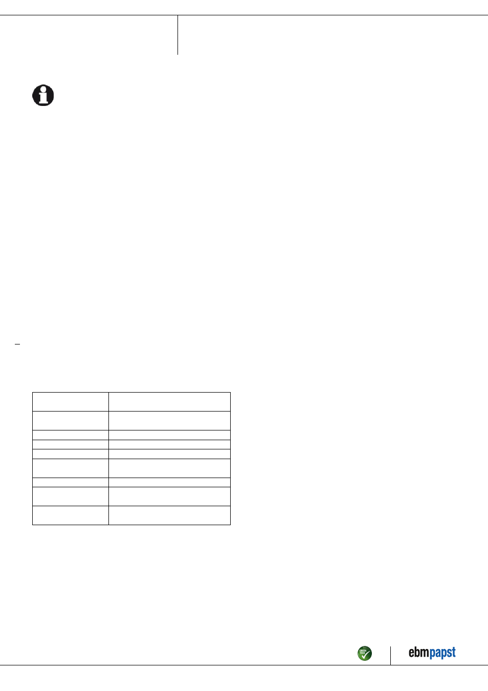
4.4 Factory settings
Factory settings with which the device is pre-set by ebm-papst.
Control mode
parameter set 1
PWM controlling
Control mode
parameter set 2
PWM controlling
Fan / device adress
1
Max. PWM / %
100
Min. PWM / %
5
Save set value to
EEPROM
Yes
Set value control
Analogue (linear)
Control function
parameter set 1
Positive (heating)
Control function
parameter set 2
Positive (heating)
Item no. 50876-5-9970 · Revision 74898 · Release 2013-08-20 · Page 7 / 10
ebm-papst Mulfingen GmbH & Co. KG · Bachmühle 2 · D-74673 Mulfingen · Phone +49 (0) 7938 81-0 · Fax +49 (0) 7938 81-110 · [email protected] · www.ebmpapst.com