Operating instructions – ebm-papst M3G112-GA53-72 User Manual
Page 5
Operating instructions
M3G112-GA53-72
Translation of the original operating instructions
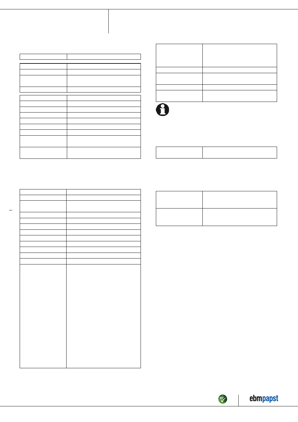
3.2 Nominal data
Motor
M3G112-GA
Phase
1~
Nominal voltage / VAC
230
Nominal voltage
range / VAC
200 .. 277
Frequency / Hz
50/60
Type of data definition
ml
State
prelim.
Speed / min
-1
3000
Power input / W
1330
Power output / W
1100
Current draw / A
5.8
Rated torque / Ncm
350
Min. ambient temperature
/ °C
-25
Max. ambient temperature
/ °C
40
ml = Max. load · me = Max. efficiency · fa = Running at free air
cs = Customer specs · cu = Customer unit
Subject to alterations
3.3 Technical features
Mass
14.8 kg
Size
112 mm
Material of electronics
housing
Die-cast aluminium
Housing material
Die-cast aluminium
Direction of rotation
Counter-clockwise, seen on shaft
Type of protection
IP 55
Insulation class
"B"
Humidity class
F3-1
Mounting position
Any
Cooling bore / aperture
Rotor-side
Operation mode
S1
Motor bearing
Ball bearing
Technical features
- Output 10 VDC, max. 10 mA
- Output 20 VDC, max. 50 mA
- Output for slave 0-10 V
- Tach output
- Input for sensor 0-10 V or 4-20 mA
- Alarm relay
- Integrated PID controller
- Motor current limit
- PFC, active
- RS485 MODBUS RTU
- Soft start
- Control input 0-10 VDC / PWM
- Control interface with SELV potential
safely disconnected from the mains
- Over-temperature protected
electronics / motor
- Line undervoltage / phase failure
detection
Touch current acc.
IEC 60990 (measuring
network Fig. 4, TN
system)
<= 3.5 mA
Electrical leads
Via terminal box
Motor protection
Thermal overload protector (TOP) wired
internally
Protection class
I (if earth wire is connected by customer)
Product conforming
to standard
EN 61800-5-1; CE
For cyclic speed loads, note that the rotating parts of the device
are designed for maximum one million load cycles. If you have
specific questions, contact ebm-papst for support.
3.4 Mounting data
; Secure the mounting screws against accidentally coming loose (e.g.
by using self-locking screws).
Strength class for
mounting screws
8.8
You can obtain additional mounting data from the product drawing if
necessary.
3.5 Transport and storage conditions
; Use the device in accordance with its protection type.
Max. permissible
ambient motor temp.
(transp./ storage)
+ 80 °C
Min. permissible
ambient motor temp.
(transp./storage)
- 40 °C
Item no. 50876-5-9970 · Revision 74898 · Release 2013-08-20 · Page 5 / 10
ebm-papst Mulfingen GmbH & Co. KG · Bachmühle 2 · D-74673 Mulfingen · Phone +49 (0) 7938 81-0 · Fax +49 (0) 7938 81-110 · [email protected] · www.ebmpapst.com