Operating instructions – ebm-papst M3G084-FA33-82 User Manual
Page 7
Operating instructions
M3G084-FA33-82
Translation of the original operating instructions
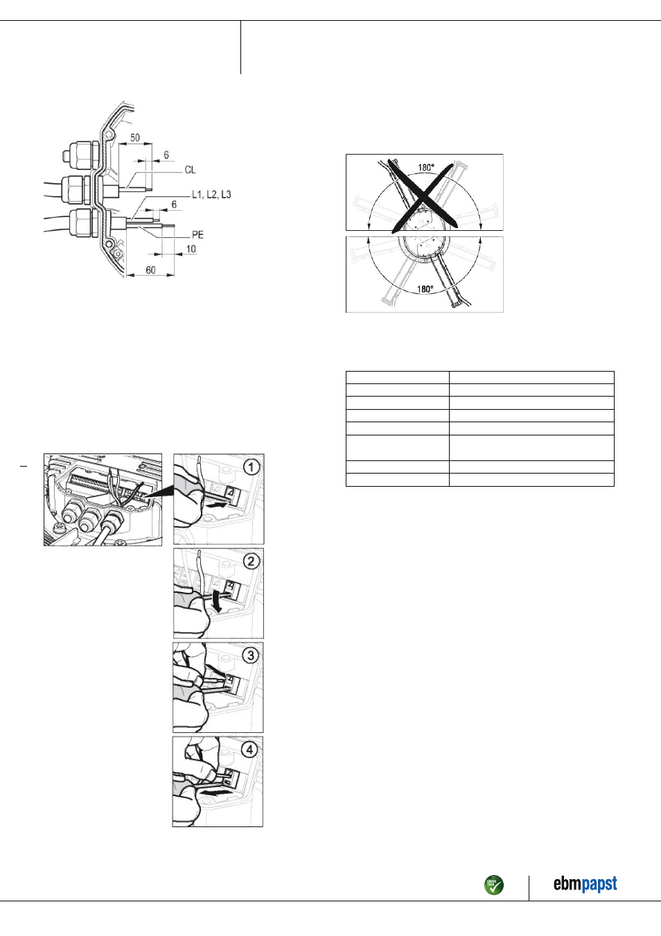
Fig. 1: Recommended stripping lengths in mm (inside the terminal box)
Legend: CL = control lines
4.3.2 Connecting cables with terminals
; Remove the cap from the screwed cable gland.
Remove the cap only in those places where cables are inserted.
; Insert the line(s) (not included in the standard scope of delivery) into
the terminal box.
; First connect the "PE" (protective earth) connection.
; Connect the lines to the corresponding terminals.
Use a screwdriver to do so.
During the connection work, ensure that no cables splice off.
Fig. 2: Connecting the wires to terminals
; Seal the terminal box.
4.3.3 Cable routing
No water may penetrate along the cable in the direction of the cable gland.
When routing the cable, ensure that the screwed cable glands are
arranged at the bottom. The cables must always be routed downwards.
Fig. 3: Cable routing for fans installed upright.
4.4 Factory settings
Factory settings with which the device is pre-set by ebm-papst.
Operation mode
PWM controlling
Group adress
01
Fan / device adress
01
Max. PWM / %
100
Min. PWM / %
0
Save set value to
EEPROM
No
Set value control
Analog
Control function
Positive (heating)
Item no. 50845-5-9970 · Revision 79932 · Release 2013-04-18 · Page 7 / 10
ebm-papst Mulfingen GmbH & Co. KG · Bachmühle 2 · D-74673 Mulfingen · Phone +49 (0) 7938 81-0 · Fax +49 (0) 7938 81-110 · [email protected] · www.ebmpapst.com