Eagle Microsystems LP4310 User Manual
Page 6
LP4310 IB.DOC
9/16/04
d. An output signal greater than 5 millivolts indicates a zero shift caused by mechanical
overload.
e. If the output signal is between 5 and 15 millivolts, the load cells zero has shifted but will
probably still continue to work.
f.
If the output signal is greater than 15 millivolts, the load cell should be replaced with a
known good one.
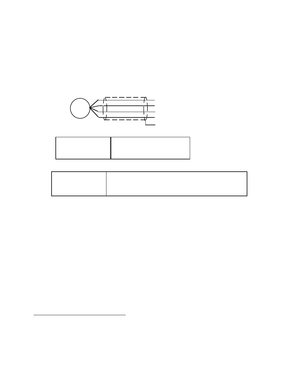
LOAD CELL VOLTAGE CHECK (WITH 15V EXCITATION)
BLACK TO WHITE:
+7.5V (EXCITATION / 2)
BLACK TO GREEN:
+7.5V (EXCITATION / 2)
BLACK TO RED:
+15V
LOAD CELL OUTPUT
GREEN TO WHITE:
LESS THEN +/- 5 MILLIVOLTS (NO DEAD LOAD)
LESS THEN 25 MILLIVOLTS (EXACT OUTPUT
VOLTAGE DEPENDS ON DEAD LOAD WEIGHT)
BLK -EXT
GRN +SIG
RED +EXT
YEL SHLD
WHT -SIG
LOAD
CELL
LOAD CELL WIRING
FIGURE 4
N O T E :
If the load cell's zero has shifted due to a mechanical overload, the reason for the
overload should be determined before a new load cell is installed.
4.2 REPLACING THE LOAD CELL
Call the factory to advise that the load cell is defective. Report model and serial numbers for both load cell
and scale.
1.
Remove all weight from scale.
2.
Stand the scale on its side. Use caution; make sure that the hook-up cable is not being damaged.
3.
Disconnect the wires of defective load cell being replaced. Gently pull cable out of the frame.
4.
Use 3/4 wrench to remove 2 hext head cap screws which secure load cell to frame.
5.
Install new load cell using 35 ft. lbs. torque to screws.
6.
Insert leads into terminal as before and tighten.
7.
With a screw driver, adjust the leveling foot until scale is level.
SECTION 5.0 SPECIFICATIONS
PHYSICAL SIZE:
Model LP4310