Eagle Microsystems LP4310 User Manual
Page 5
LP4310 IB.DOC
9/16/04
1. Inaccurate but repeatable weight readings:
a.
Adjust span on read-out (see instrument manual)
2. Blank or drifting display:
a.
Consult the instrument manual.
b. Look for loose connection in hook-up cable at the instrument.
c.
Test for bad load cell (Section 4.1).
SECTION 4.0 SERVICING
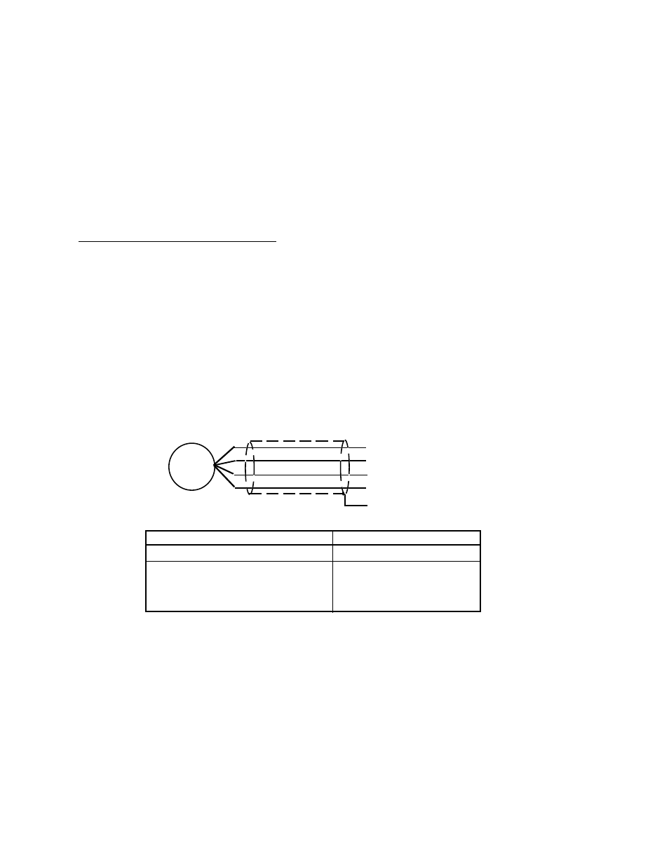
4.1 Checking the load cell.
1. Load Cell resistance test:
a.
Disconnect the load cells from the instrument and measure the resistance as shown in
Figure 3.
b. Any electrical leakage between the leads and the load cell case is usually caused by moisture
leakage into the load cell or by moisture in a damaged load cell cable.
c.
If a load cell does not pass the above resistance tests, replace it with a known good one.
RED TO BLACK
360
GREEN TO WHITE
350 +/- 5
Ω
RED, BLACK, GREEN,
WHITE, OR YELLOW
GREATER THAN 200
TO CASE
MEGOHMS *
* Using a portable Ohm meter on highest range you should read infinity
LOAD CELL WIRING
BLK -EXT
GRN +SIG
RED +EXT
YEL SHLD
WHT -SIG
LOAD
CELL
LOAD CELL RESISTANCE CHECK
Ω
FIGURE 3
2. Load Cell zero shift test:
a.
Remove all the weight from the load cell and measure the output as shown in
Figure 4.
b. Connect a DC power supply of 10 or 15 volts to the Red (+) and Black (-) excitation load cell
leads.
c.
The measured output between the Green (+) and White (-) signal leads should be less
than 5 millivolts.