Expander – Drawmer DL231 Dual Expander/Compressor User Manual
Page 7
DL231 OPERATORS MANUAL
5
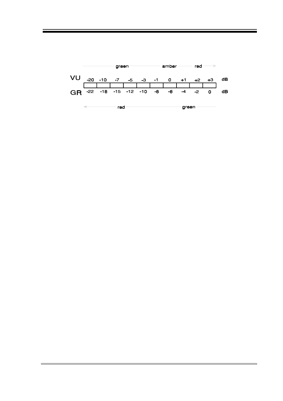
LED BAR DISPLAY is a dual function facility which measures output level (input level if
bypass is selected) or gain-reduction, selectable by the display
switch.
NB
i.
The VU meter and threshold controls are calibrated to show 0VU at +4dB
ii.
In the gain reduction mode, all the red LED’s are very slightly illuminated at all
times. This is quite normal and does not indicate a fault condition.
EXPANDER
THRESHOLD
(+10 to -40 dB) sets the point at which gain reduction takes place.
Signals above threshold pass un-attenuated unless compression
occurs..
RATIO
A three position switch selects ratios of 1:2, 1:5 or 1:20 provides
gating characteristics. Gating can be regarded as the opposite of
limiting.
ATTENUATION
(Attn) a three position switch sets the maximum attenuation of 10,
20 or 40dB.
FUNCTION
selects ‘side-chain listen’, normal (expander in operation) and off
(expander bypassed).
ATTACK
time is completely automatic. See introduction.
RELEASE
time is semi-automatic, matched to the compressor release and is
adjustable via the compressor release
VISUAL DISPLAY
is by means of three LED’s arranged in a horizontal ‘traffic light’
configuration. Green indicates zero expansion, whilst yellow shows
gain reduction of 50%, referring to the attenuated setting and red
100%.
STEREO LINK
couples the control circuits of both compressors to prevent image
shifting when treating stereo material on a final mix. The peak
limiters can also be used if desired but they remain independent.
Operational controls should be set the same on both channels when
linked.
SIDE-CHAIN EQ
may be applied to expanders and compressors via insert points at
the rear of the unit. Connection are via stereo jack ( Rind - send. Tip
- return)