Drawmer 1961 Vacuum Tube Equaliser User Manual
Page 8
1961 OPERATORS’ MANUAL
6
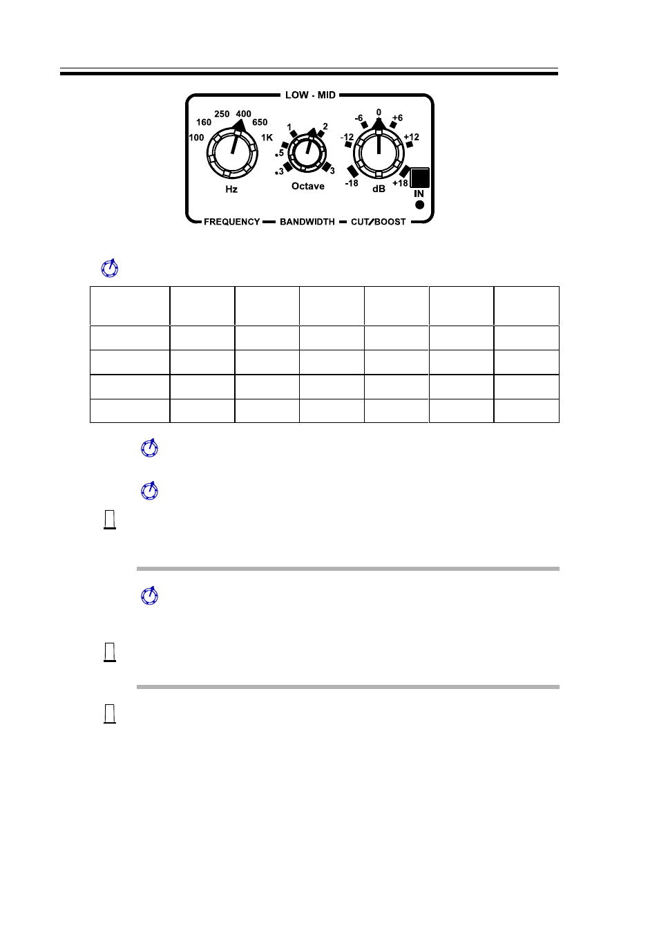
Hz:
Frequency selector switch. Available frequencies are:
Frequency
Switch
1st
position
2nd
position
3rd
position
4th
position
5th
position
6th
position
Bass
20Hz
32Hz
50Hz
80Hz
125Hz
200Hz
Low-Mid
100Hz
160Hz
250Hz
400Hz
650Hz
1kHz
High-Mid
500Hz
800Hz
1.2kHz
2kHz
3.2Khz
5kHz
Treble
2.5kHz
4kHz
6kHz
10kHz
15kHz
25kHz
Octave:
Filter bandwidth (or 'Q') control. Variable between 0.3 and 3
octaves.
Cut/Boost:
Filter cut or boost control providing
±
18dB of control.
In:
Each filter section has an associated Bypass switch. When the
switch is pushed in, the red LED below will illuminate, indicating
that the equaliser is in circuit.
Low-Pass:
This is a continually variable 12dB per octave shelving, low -
pass filter which may be adjusted over the range 2.5kHz to
56kHz.
In:
This Bypass switch, when pushed in will illuminate the red LED,
indicating that the Low - Pass is in circuit.
EQ
Out:
This acts as a Master Bypass switch. If the switch is depressed,
the associated Out LED illuminates. This indicates that all the
equaliser sections, including the high and low-pass filters, are
out of circuit. This Master Bypass switch also bypasses the tube
section of the output stage; if it is desired to use the tube output
stage without equalisation, the EQ Master Bypass should be left
In circuit and all the individual Bypasses should be switched Out
of circuit. W hen the Master Bypass switch is set to Out, the
individual equaliser status LEDs are extinguished.