Fuses, Audio connections – Drawmer 1961 Vacuum Tube Equaliser User Manual
Page 5
1961 OPERATORS’ MANUAL
3
FUSES
The mains fuse should be a class 3, 250 Volt, Time delay type, with a body size of
20mm x 5mm, at the correct rating for the mains input voltage. It is very important
that this fuse complies with IEC127-2. Remember that, in the unlikely event of the
unit developing a fault, it is normal for the mains fuse to blow and the unit must be
serviced by a qualified service technician.
For added protection the 1961 is also fitted with silicon re-setable fuses. Under
certain conditions, - eg. intermittent mains power, faulty mains cable - these fuses
will 'trip', effectively removing power from the internal circuitry. If this should happen,
the silicon fuses will automatically reset after switching off the unit for 15 to 30
seconds and then switching back on again. The fuses will probably never trip.
Occasionally the fuses might trip repetitively due to an internal fault, in which case
the unit will need attention from a service technician before the silicon fuses will
reset.
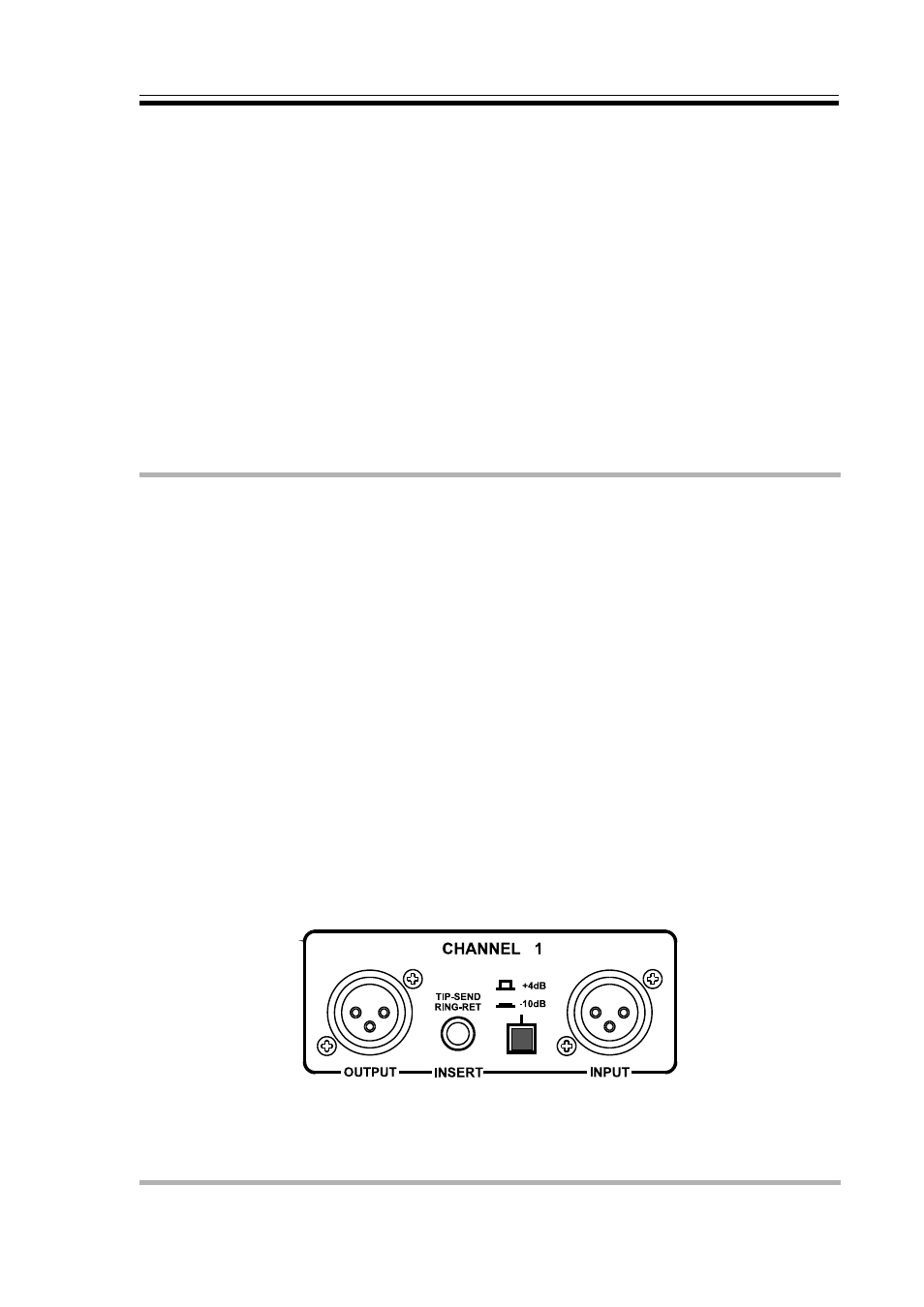
AUDIO CONNECTIONS
The inputs and outputs are electronically balanced XLRs where pin 1 is screen, pin 2
hot, pin 3 cold and the XLR shell is connected to chassis. The operating level is
nominally +4dBu. Balanced use is recommended. The 1961 fully conforms to the
EMC standards, if you propose to use the unit where it maybe exposed to high levels
of disturbance such as found close to TV and radio transmitters we suggest that the
screen of the signal cable is connected to the chassis connection on the XLR type
connector.
A further connection point is provided in the form of the Audio Insert jack on the rear
panel. This is a stereo jack socket wired such that the Ring carries the input to the
1961 and the Tip carries the output. W hen a plug is inserted, the XLR input for that
channel is disconnected. The Audio Insert point may be connected directly to the
side-chain access point of a Drawmer 1960 using a stereo jack cable wired with
screened cable where the tip connects to the tip; ring connects to ring and the screen
is connected at both ends. Alternatively, the same type of stereo jack lead may be
used to connect the 1961 Audio Inserts to the +4dBU Signal Insert point of the 1960
allowing the two units to be used in series. In this latter configuration, only the
balanced audio connections of the 1960 are used; the 1961 is connected only via its
Audio insert points.
If earth loop problems are encountered, do not disconnect the mains earth. Try
disconnecting the signal screen on one of the cables connecting the outputs of the
1961 to the patchbay. If such measures are necessary, balanced operation is
recommended.