D.w. fearn – D.W. Fearn VT-2 User Manual
Page 23
D.W. FEARN
VT-1 & VT-2 Microphone Preamplifers
23
4 .
O P E R AT I O N
Input
Since the input cable will be carrying very low level audio, it is important that a well-shield-
ed cable is used. There should be no additional connectors, patch jacks, switches, etc.
between the microphone and the VT-2 input. This can be achieved with a dedicated line from
an XLR connector in the studio to each VT-2 in the control room. Although long input cable
runs have little effect on the performance of the VT-2, it is preferable to keep the input line
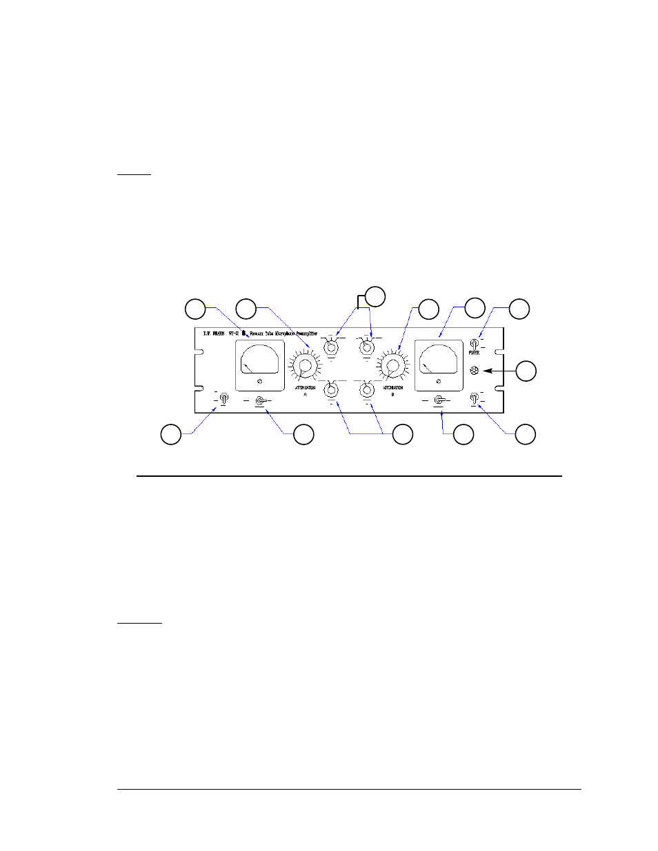
Figure 2. VT-2 front panel controls and indicators
1
6
3
2
3
6
8
5
4
5
1
7
as short as possible. One successful method is to place the VT-2 in the studio with only a
short cable to the microphone. Line level from the VT-2 output is then fed back to the con-
trol room. Avoid locating the VT-2 where it will be subjected to high sound levels or excessive
vibration (such as on a drum riser).
Output
The output of the VT-2 is line level, transformer balanced. Note that vacuum tube equipment
is more sensitive to load impedance than solid state units. The VT-2 design was optimized for
feeding a balanced bridging input (20k ohms or greater). When feeding a 600 ohm load,
there may be a slight degradation of some
of the specifications. In modern studio equip-
ment, bridging line inputs are universal. If the device being fed by the VT-2 has an input
termination switch, that switch should be in the “off” position.