Figure 2.7 • internal wiring diagram, Figure 2.8 • field wiring diagram – Crown Verity DSC Series User Manual
Page 18
18
19
19
DSC
Series
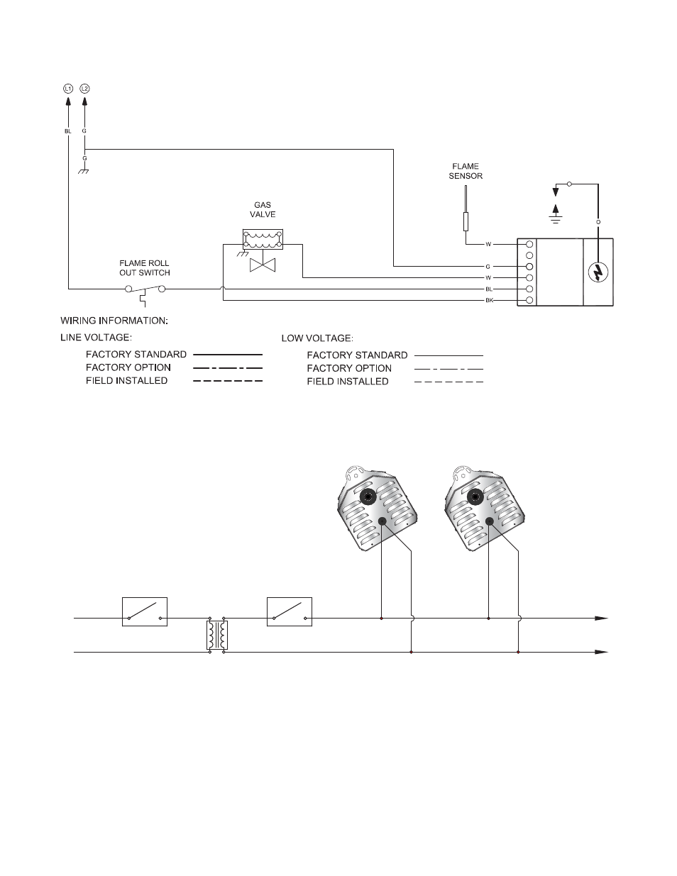
ADDITIONAL HEATERS
REQUIRE PROPERLY SIZED
24 VAC TRANSFORMER
OPTIONAL
LOW VOLTAGE
SWITCH OR TIMER
LINE VOLTAGE
SWITCH OR TIMER
EXTERNAL
TRANSFORMER
L1
L2
120
VAC
24
VAC
HOT
3.0
Maintenance
•
Wiring Diagrams
Figure 2.7
•
Internal Wiring Diagram
IGNITION
MODULE
SPARK
SENSE
GROUND
VALVE -
THERMOSTAT
VALVE +
Figure 2.8
•
Field Wiring Diagram
Starting Amp Draw: 0.65 Amp
Running Amp Draw: 0.48 Amp
Field Wiring:
1
24 VAC/20VA transformer (.8 Amp) per heater is required (supplied by installer).
2
Maintain electrical polarity when hooking up multiple heaters.
3
Allow heaters to be switched by zones for heating flexibility.
4
Do not attempt to install transformer inside of heater.
IGNITION
MODULE
SPARK
SENSE
GROUND
VALVE -
THERMOSTAT
VALVE +
IGNITION
MODULE
SPARK
SENSE
GROUND
VALVE -
THERMOSTAT
VALVE +
IGNITION
MODULE
SPARK
SENSE
GROUND
VALVE -
THERMOSTAT
VALVE +