Cub Cadet Fabricated Deck InDirect Injection Diesel User Manual
Page 21
21
2.
Leaking Tires: When a flat tire occurs, repair
or replace immediately. The normal procedure
is to remove the wheel and replace it with a
spare. Take the leaking tire to a maintenance
area and repair. If a tire is getting soft, park
the mower on the nearest level, paved area. If
the leaking tire is on a traction wheel, put
blocks on each side of the opposite traction
wheel and jack up the tire that leaks about an
inch off the ground. Loosen and remove the
lug nuts and remove the wheel. Mount a
spare wheel and tire, replace the lug nuts, and
using a torque wrench, tighten them to 60
±
10 lb-ft.
If the leaking tire is on a front caster wheel,
block both traction wheels and raise the
caster wheel so that the tire is an inch off the
ground. Loosen and remove the locknut from
the axle assembly and pull the axle assembly
from the caster yoke. The wheel and two
spacer sleeves will drop free. Slip the axle
assembly through one side of the caster
yoke, through a spacer sleeve, a spare
wheel, the other spacer sleeve and finally
through the other side of the caster yoke.
Then tighten the locknut on the end of the
axle assembly.
Lower the mower off the jack and continue
mowing. The wheel with the leaking tire
should be taken to the maintenance area, the
tire inflated to 20 psi and the wheel placed in
a large bucket of water. Carefully inspect the
tire, rim and valve for escaping air bubbles
which indicate a leak. Mark each leak with a
yellow marking crayon and then deflate the
tire to 8 psi and repeat the inspection. If the
leaks you find are pin hole size to 1/16"
diameter, the tire can be repaired using an
aerosol can of tire inflater and latex sealer
available from any auto supply store. Follow
the directions on the can. If the leaks are
larger than 1/16" diameter, the tire can be
repaired with rubber plugs also available in a
kit from any auto supply store. If the tire bead
is damaged, a tube will have to be installed in
the tire or the tire will have to be replaced.
3.
Creeping: Creeping is the slight forward or
backward movement of the mower when the
throttle is on and the lapbars are in the
opened-out position. If your mower creeps do
the following.
a. Jack up rear of unit.
b. Place Lapbars in neutral opened-out posi-
tion.
c.
Locate jam nuts. (Reference control
assembly in parts list).
d. Loosen jam nuts on both ends of rod con-
nectors. See Control Assembly in the Illus-
trated Parts Book (ONLY if mower creeps.)
e. Start unit and push throttle all the way on.
f.
If unit creeps forward rotate rear rod con-
nectors counter-clockwise. And if unit
creeps in reverse, rotate clockwise.
Adjust the appropriate rod connector. The
left rod for the left side of the mower and
the right rod for the right side of mower.
Afterward, retighten jam nuts.
E. Brakes
While the mower is in motion, all braking is performed
dynamically through the hydraulic pumps and traction
motors, controlled by the two steering levers. When the
mower is parked with the engine shut off, the hydraulic
system locks the traction wheels.
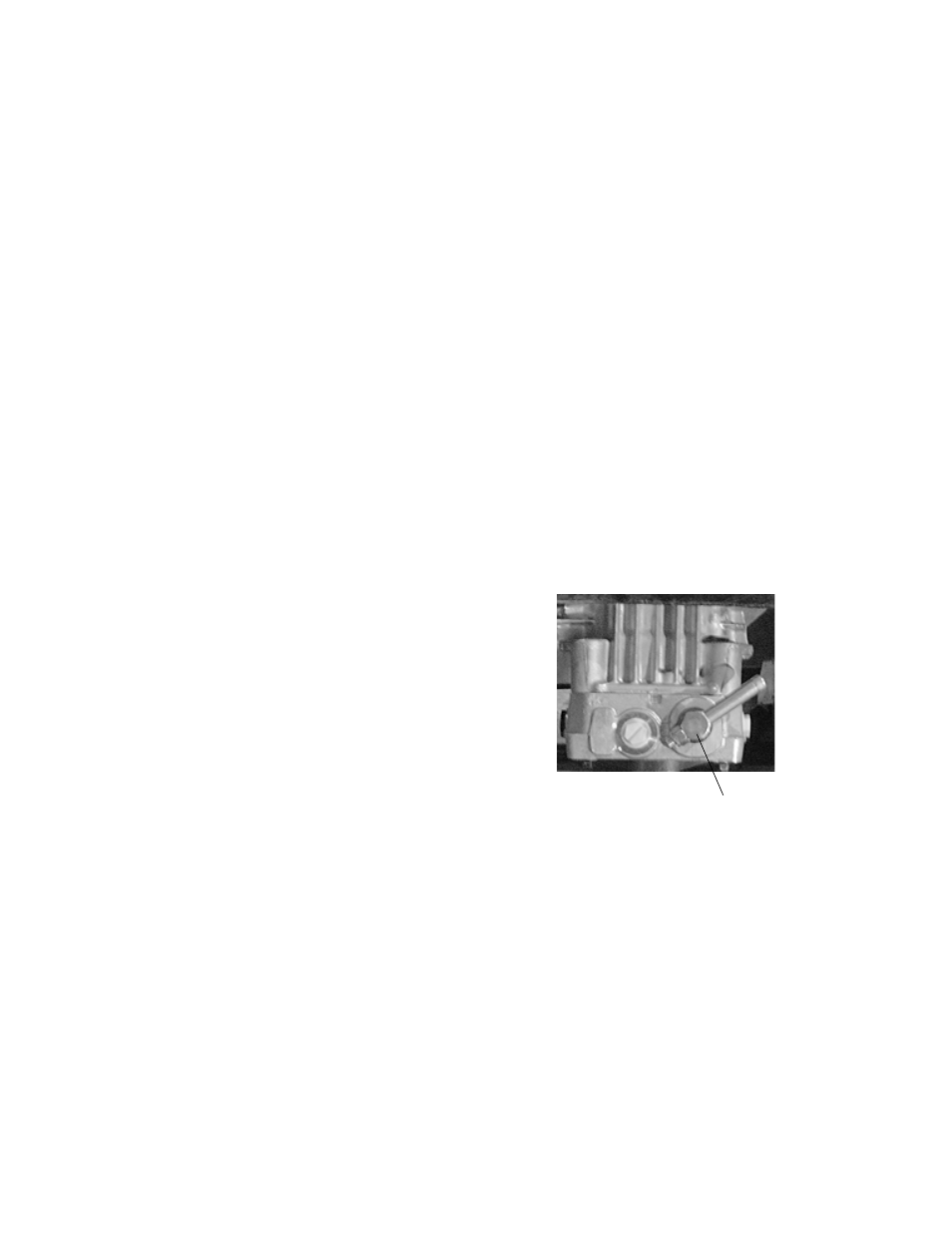
Note:
To move the mower forward or in
reverse by pushing, you must release the
dynamic braking. Locate the valves on the
pump. Turn valves counter-clockwise one
quarter turn to push the unit. After pushing
the mower to the desired location, return both
valves to the operating position (See photo
below)
.
When the mower is parked with the engine running
and the steering levers opened out in the neutral
position, the parking brakes should be applied. The
parking brakes are drum-type brakes mounted on
each traction wheel.They are both engaged by the
same operating lever.
1.
Adjustments: The parking brake handle is an
overcenter lever that should engage with
moderate force.
Note:
To increase parking brake capacity
tighten the brake rods going back to the brake
arms equally. Tighten rods one full turn and
check parking capacity. Repeat Step.
To adjust either brake individually, tighten the hex nut
in a clockwise direction one full turn looking down the
Hydro Release Valve