Connector descriptions – Cooler Master Extreme Power 430 User Manual
Page 6
5
User’s Manual / English
4.
If the power supply does not work properly, please contact our service center immediately.
5. Connector Descriptions
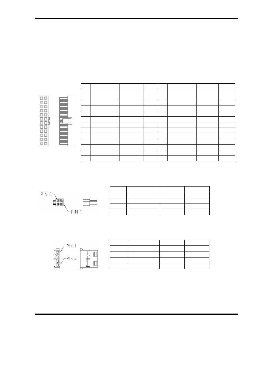
5.1 P1 (Motherboard) Connector
Pin Description
Color AWG Pin
Description Color AWG
1 +3.3V Orange
18
13
+3.3V
+3.3Vs
Orange
Brown
18
22
2 +3.3V Orange
18
14
-12V Blue 18
3 GND
Black 18
15
GND Black 18
4 +5V
Red 18
16
PS-ON
Green
18
5 GND
Black 18
17
GND Black 18
6
+5V Red
18
18
GND
Black
18
7 GND
Black 18
19
GND Black 18
8 P.G. Gray
18
20
-----
---- ----
9 +5Vsb Purple 18
21
+5V
Red 18
10 +12V
1
Yellow
18
22
+5V Red 18
11 +12V
1
Yellow
18
23
+5V Red 18
12 +3.3V Orange 18
24
GND Black 18
5.2 P2 (+12V Power) Connector
Pin Description Color AWG
1
GND Black 18
2 GND Black 18
3 +12V
2
Yellow 18
4 +12V
2
Yellow 18
5.3 P3, P4, P5, P7, P8, P9 (Peripheral) Connectors
Pin Description Color AWG
1 +12V
1
Yellow 18
2 GND Black 18
3 GND Black 18
4 +5V Red 18
PIN 1 PIN 13