Wiring, Learn limits, Force adjustment – LiftMaster RSW12V Residential / Light Commercial Swing Gate Operator with Battery Backup User Manual
Page 2: Test, Wiring в, Learn limits d, Programming, Ж warning
Attention! The text in this document has been recognized automatically. To view the original document, you can use the "Original mode".
ж WARNING
To protect against fire and electrocution:
• DISCONNEQ power and bottery BEFORE installing or servicing
operator.
For continued protection against fire:
• Replace ONLY with fuse of some type and rating.
Second Operator
(Optional)
Use the Dual Gate Wiring Kit (refer to the
occessoty page a( the installatian manual).
m [m ЯйЗ ■ I----
BI
o
UL ---
_l»n liJ— il
Relay Adapter Mudule
j
®
@
Ф
w
Ф
@
Ф
Ф
Ф
IWTE2
^^|> SATEl
SO 0 0'S™
<0 0>
E
FORCE
A,
OFF MAX
ON OFF
LOW ВАТТ
TIMER TO
CLOSE
)FF UA)
О m
о
«-0
STOpQ
CTRLPWR
cmLPwn
c
в
Black
Bottery (provided)
POWER WIRING OPTIONS
_ 1 SHADOW Q
®li
Earth Ground Rod
Optional second 7AH,12Vhuttery
(not provided)
нот Ом зшьтуШрпуМ)
cm be used in phce of Ню 7AH batteries.
a INTERNAL RECEPTACLE
EXTERNAL RECEPTACLE
SOLAR PANEL
(NOT PROVIDED)
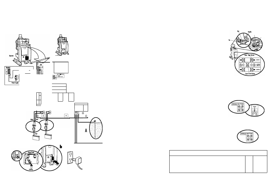
WIRING
В
EARTH GROUND ROD
Use the proper earth ground rod for your local area. The
ground wire must be a single, whole piece of wire. Never splice
two wires for the ground wire. If you should cut the ground
wire too short, breok it, or destroy its integrity, replace it with a
single wire length.
NOTE:
If the operator is not groonded properly the range of
the remote controls will be redoced.
] Install the earth ground rod within 3 feet of the operator.
2 Attach the graund wire ta the graund terminal on the
control board.
POWER WIRING OPTIONS
This operator is capable of being powered by the
1
receptacle, on external receptacle or a solar
(not provided).
a
1
INTERNAL RECEPTACLE
Remove the access panel.
2 Connect AC power to the operator:
• Connect the green wire to the ground screw in the
access panel.
• Connect the black and white wires together with
wire nuts.
3
Replace the access panel.
^ Connect the wires from the transformer to the
AC PWR/SOLAR terminal located on the control board.
5 Plug the transformer into the internol receptacle.
EXTERNAL RECEPTACLE
] Run low voltage wire between the transformer and the
operator.
2 Connect the wires from the transformer to the
AC PWR/SOLAR terminal located on the control board.
3 Plug the transformer into the external receptacle.
C
SOLAR PANEL
Not provided. See Accessories in the Installation Manual.
[ CONNECT BATTERIES
] Locate the battery plug.
2 Connect the battery plug to either connector on the control
board.
01-3531SD
©2010 The Chamberlain Graup, Inc.
All Rights Reserved
LEARN LIMITS
D
SINGLE GATE RIGHT-HAND SIDE
] Close the gate. Make sure the operator arm is properly seated on the output shaft (the pin must fit into the slot). Make
sure the handle is released on the operator arm and the learn limit cam is touching the learn limit switch.
PROGRAM OPEN
2 Manually open the gate to the desired open position.
0
^
Tighten the handle on the operator arm.
Learn limit Cam
Learn Limit Switch
4
Press and release the LEARN LIMITS BUTTON. The SET OPEN
LIMIT LED will blink.
5
Press and release the LEARN LIMITS button again. The control
board will beep and the SET CLOSE LIMITS LED will blink.
PROGRAM CLOSE
5 Press and hold the GATE 1 right button to move the gate to the desired
CLOSED position. When the gate is in the desired position, release the button.
NOTE:
The GATE I right and left buttons can be used to jog the gate back
and forth as needed.
7 When gate is in the desired CLOSED position, press and release the
LEARN LIMITS button. The control board will beep and the SET CLOSE LIMITS
LED will stop blinking.
Programming is now complete. (If the SET OPEN LIMIT LED continues to blink, repeat programming.) Test the limits by
pressing the SINGLE BUTTON to open and close the gate.
FORCE ADJUSTMENT
^ ] Use the SINGLE BUTTON to open and close the gate.
2
If the gate stops or reverses before reaching the fully open or
closed position increase the force by turning the force control
slightly.
3
Run operator through o complete cycle.
TEST
p After ony adjustments are made, test the operator:
1
Use the SINGLE BUTTON to open and close the gate.
2 Test the limits by making sure the gate is stopping at the OPEN
and CLOSE limits.
3 Test the force by moking sure the gate will stop and reverse on
contact with an obstruction.
PROGRAMMING
Q REMOTE CONTROLS
] Press and release the LEARN XMITTER button (LED will light). (
2 Press the remote control button. The LED will flush and the alarm
output will activate twice.
LEARN
XMITTER
X©