Using sata port from the pcie/104 type 2 bus – Connect Tech SSD/104 User Manual
Page 11
Connect Tech SSD/104 SATA User Manual
Revision 0.00
11
Using SATA Port from the PCIe/104 Type 2 Bus
The SSD/104 SATA board has the ability to source it’s SATA channels directly from the PCIe/104 Type
Bus. This can be done via 0 ohm 0402 sized resistor population options on the PCB and allows users to
select from the TOP or BOTTOM side signals from the PCIe/104 bus. If you would like to order an
SSD/104 SATA product from Connect Tech pre-configured to use PCIe/104 Type 2, please contact
[email protected] . Otherwise the follow procedures can be performed by the end-user at their
own risk.
NOTE: These actions should only be done by trained technicians with adequate tools to be working with
0402 sized parts.
To connect SATA Port 0 from the PCIe/104 bus in a STACK UP configuration to mSATA0 please perform
the following steps:
-
REMOVE (R11& R12) (R15& R16)
-
ADD (R9, R10) (R13, R14) (R7, R8) (R4, R8)
To connect SATA Port 0 from the PCIe/104 bus in a STACK DOWN configuration to mSATA0 please
perform the following steps:
-
REMOVE (R11& R12) (R15& R16)
-
ADD (R9, R10) (R13, R14) (R3, R5) (R1, R2)
To connect SATA Port 1 from the PCIe/104 bus in a STACK UP configuration to mSATA1 please perform
the following steps:
-
REMOVE (R27& R28) (R31& R32)
-
ADD (R25, R26) (R29, R30) (R17, R18) (R19, R20)
To connect SATA Port 1 from the PCIe/104 bus in a STACK DOWN configuration to mSATA1 please
perform the following steps:
-
REMOVE (R27& R28) (R31& R32)
-
ADD (R25, R26) (R29, R30) (R21, R22) (R23, R24)
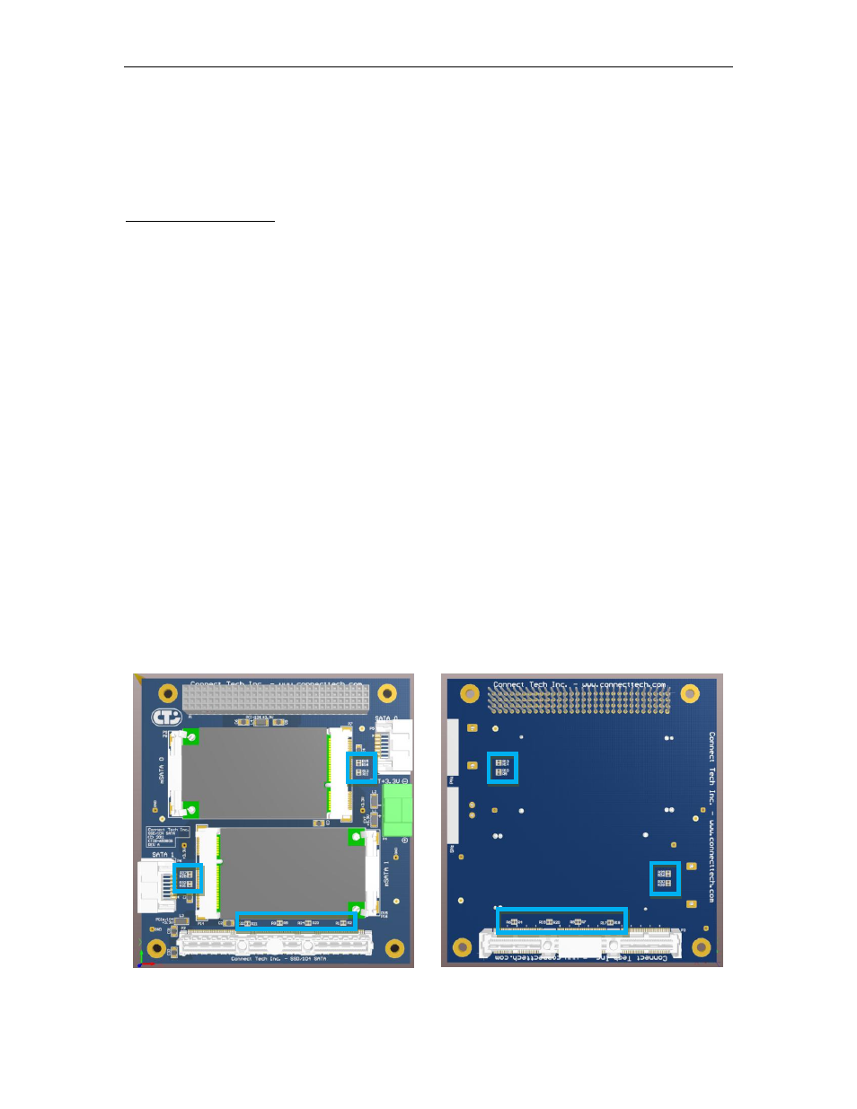
Locations of 0 ohm Resistor for PCIe/104 SATA Selection
Top Side of SSD/104 SATA
Bottom Side of SSD/104 SATA