Rear panel – Uniden UST-9000 User Manual
Page 4
Attention! The text in this document has been recognized automatically. To view the original document, you can use the "Original mode".
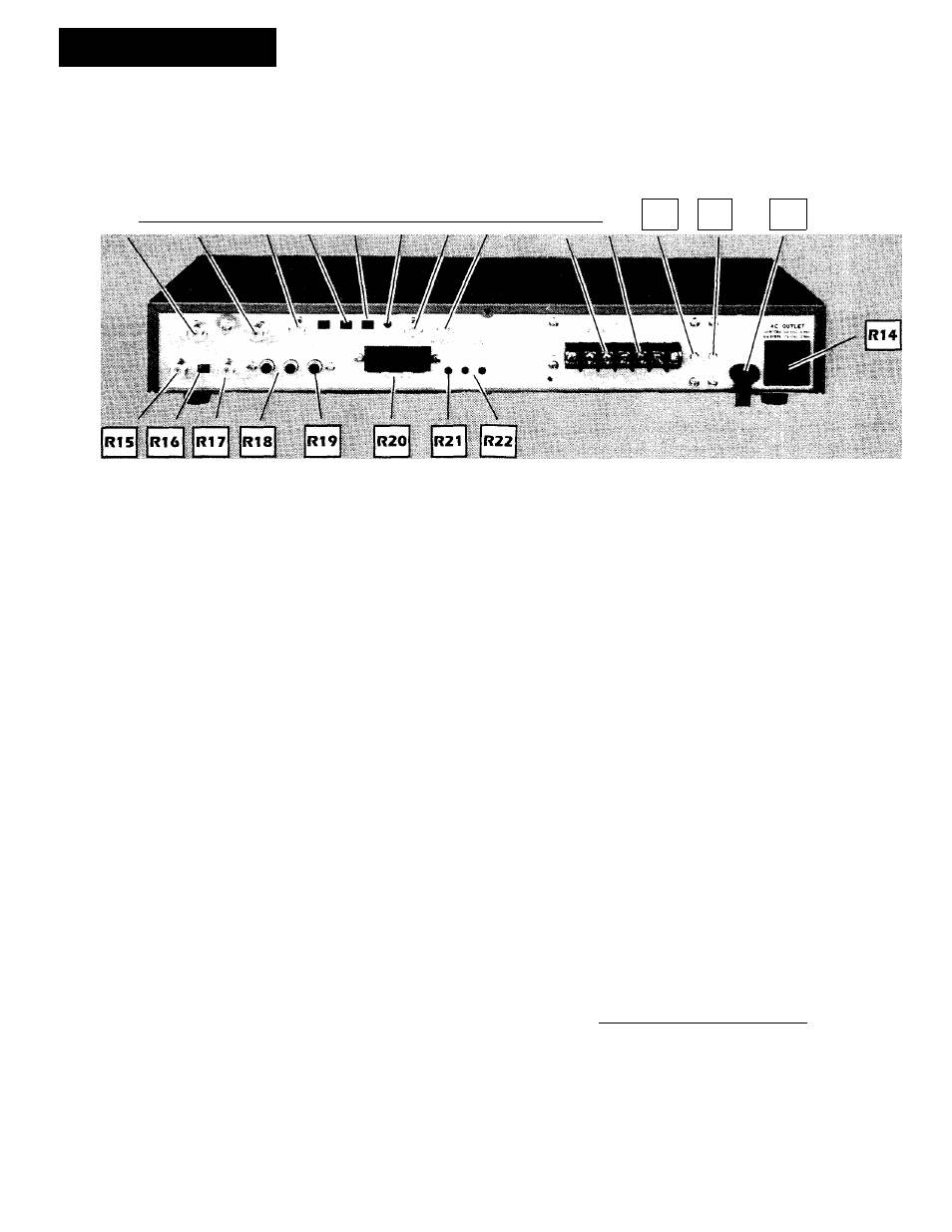
Rear Panel
0 S S I R4 I I R5 I I R6 I I rt7 11 R8 (
| R9 [ |
r
1
o
|
R11
R12
R13
Rear Panel
I?1. C Input - F type connector for the I GHz IF cable
from the LNB or the UST-524 multiple receiver unit.
R2. Ku Input - Connect the 1 GHZ IF cable from the Ku
LNB for Ku band reception.
R3. Descram Out - F type connector for composite vtd-
eo output used with a descrambling device.
R4. Tl On/Off Switch - Select On to help eliminate
microwave (terrestrial) interference, or OFF for normal
use.
R5.
18V and V/H Switch - Select the + 18V position for
single receiver installations. Select the V/H position
when using the UST-524 for multiple receiver installa
tions.
R6. CPU Reset - Press this switch to clear the central
processing unit. WARNING: WHEN THIS BUT
TON
IS
PRESSED
ALL
MEMORY
WILL
BE
ERASED.
R7.
-I- 18V - F type connector for -F 18VDC power to the
UST-524 for multiple receivers installation. When the
UST-524 is used the 18V - V/H switch must be in the
V/H position.
R8. Remote Station - F type connector for hook up of
the UST-88 remote control system which allows oper
ation of this receiver from a remote location.
R9. Motor -F and - Terminals - 36 VDC 1.5 amp max
output for actuator motor. Circuit breaker R11 controls
this circuit.
R10.
-F
B, SEN, and GND Terminals - Connect to actu
ator sensor.
R11. Actuator Circuit Breaker - Push to reset. If brea%^.
^—er trips, check the antenna and actuator to make sure
they are operating properly.
R12. Main Circuit Breaker - Push to reset.
R13. AC Power Cord - Connect to any 110 - 120V
household AC outlet. Do not connect to an outlet con
trolled by a wall switch.
R14. AC Outlet. - Unswitched power for other equip
ment such as a monitor or VCR. When the power to
the UST-9000 is turned off this outlet remains on.
R15. RFOut - F type connector to wire satellite receiver to
the VHF antenna terminal of television.
R16. CH 3/4 Switch - Select either channel 3 or 4 depend
ing upon your television set.
R17. Ant. In - F type connector for external VHF TV
antenna. When the power is off signal is connected to
RF out (R15|.
R18. Audio 1 and 2 Output - RCA type connectors for
external audio equipment, VCR or monitor.
R19. Video Output - RCA type connector for an external
monitor. _VCR or descramblinq devjce.
R20. -F6V, Pulse, and GND Terminals - Connectors
for a servo motor type polarization device. Voltage
automatically turns off 4 seconds after polari?-'
changes.
i
R21. Counter Clear - Press to erase the limits for antenna
travel and to reset the counter to 000.
R22. Up and Down Limit - Set the east and west limit of
travel for the antenna.