Channel assignment, Models available: controls and connections – Channel Plus 5545 User Manual
Page 5
If an error has occurred or an incorrect channel is
entered, the LED will flash quickly for a second and
return to the previous settings.
If two adjacent channels are selected, the unit will
accept the entry but will blink the LEDs of channels
that are too close. If this happens, re-program one
of the channels to move it away from the other.
To readback modulator
C
channel assignment
(example: C has been programmed to channel
)
108
Hold
button down
for 5 seconds, then release.
program
LED blinks time and pauses
1
LED blinks times
8
LED blinks
times, pauses
(“10” is read back as 0)
10
Press
button until
channel LED is on
select
C
select program
A
B
C
D
select program
A
B
C
D
select program
A
B
C
D
select program
A
B
C
D
select program
A
B
C
D
Valid Channels:
Channel Spacing:
Error indication:
Channel number
readback:
14-64:
UHF channels
65-125: CATV channels
95-99:
not valid
Skip at least one number between channels.
Channels 14 and 16: OK.
Channels 14 and 15: Illegal.
A readback mode will display the current channel
assignments.
8
select
program
IR
pll frequency control
A B C D
model 5545 quad digital modulator with ir output
TM
The
are digitally-tuned video modulators that convert
any baseband video and audio signal to a user-selected UHF, or Ultraband CATV.
An internal quartz crystal reference oscillator and PLL circuitry ensure drift-free
performance. The user selects the output frequency (channel) using the "
"
button to choose which modulator and the "
" button to enter the number of
the desired channel. Any TV connected to the output via coax can receive the
signals, when the TV is tuned to the proper channel.
5525
2 channel modulator with IR
5545
4 channel modulator with IR
ChannelPlus 5500 Series
select
program
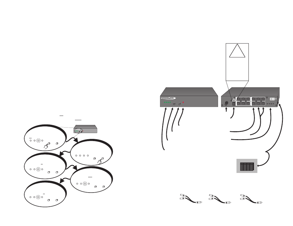
Models available:
Controls and Connections:
(Model 5545 shown)
RF output
Select button chooses
the modulator.
Program button enters
the channel number
Modulator LEDs show which
modulator is selected
IR LED
Power supply
15VDC 600mA (Model 5525)
15VDC 900mA (Model 5545)
Audio inputs: Right and Left
Terminating jumpers (remove for hi-Z)
(on side of unit)
Option:
To connect the video and audio to a local monitor, use RCA type ‘Y’ adaptors and
remove the ’LOOP’ jumper for corresponding channel.
VIDEO
AUDIO L
AUDIO R
Video inputs
select
program
IR
pll frequency control
A B C D
model 5545 quad digital modulator with ir output
TM
IR repeaters
CH
C
CH
D
VIDEO
AUDIO L
AUDIO R
CH
A
CH
B
VIDEO
AUDIO L
AUDIO R
OUTPUT
900mA
Remove jumper for Hi-Z
(See manual)
A B C D
IR REPEATERS
C
A
D
B
5
!
!
THE EXCLAMATION
POINT WITHIN THE
TRIANGLE IS A
WA R N I N G S I G N
ALERTING YOU OF
I M P O R T A N T
I N S T R U C T I O N S
ACCOMPANYING
T H E P R O D U C T.
POWER
15VDC