Wiring, Maintenance – Chromalox PF411-10 User Manual
Page 2
WIRING
Electric Shock Hazard. Heater case must be effec-
tively grounded in accordance with the National
Electrical Code to avoid hazard of electric shock.
NOTE: All electrical wiring must be installed in accordance with
the National Electrical Code and local codes by a qualified person.
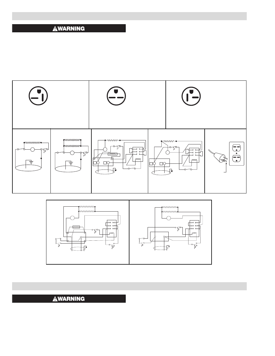
1. This heater is for use on 120, 208 or 240 volts. (See heater
nameplate.) The cord has a plug similar to one shown in
Figure 10. (Consult Table A for actual plug configuration.) No
adapter is available for these blade type configurations, and
none should be used.
An appropriate 20A @ 125V, 15A @ 250V or 20A @ 250V
grounding outlet must be used. When properly installed, it
provides a ground connection through the cord to the heater to
protect the operator from electric shock.
2. Connect heater according to the voltage and frequency speci-
fied on the nameplate and using the appropriate wiring dia-
gram (below).
MAINTENANCE
1. Hazard of Electric Shock. Disconnect
all power before attempting to service this heater.
Do not attempt to service heater while unit is operating as
there is hazard of electric shock, injury from operating fan and
burns from hot heating elements.
2. Following long periods of idleness, heater should be vaccu-
umed before start-up, to remove accumulated combustible
particles which otherwise may smoke or incinerate on initial
heat up.
3. When heater is not in use, store in safe location to prevent
heater and/or power cord damage.
4. HF heaters use permanently lubricated motors, do not attempt
to lubricate.
Grounding Pin
Figure 3
Figure 4
Figure 5
NEMA 5-20P
NEMA 6-15P
NEMA 6-20P
20A
125V
15A
250V
20A
250V
Figure 6
Figure 7
Figure 8
Figure 9
Figure 10
M
Element
Cutout
Switch
Cord Set
When Furnished
M
Elements
Cutout
Switch
Cord Set
When Furnished
M
Element
Cutout
Switch
L1
L2
Resistor
Contactor
Cord Set
When Furnished
M
Element
Cutout
Switch
L1
L2
Contactor
Cord Set
When Furnished
Figure 11
Figure 12
M
Elements
Cutout
Fan Delay
Resistor
Contactor
Cord Set
When Furnished
Toggle
Switch
Optional Remote
Thermostat
By Others
1
3
2
4
L1
L2
Terminal Block
2
1
3
M
Elements
Cutout
Fan Delay
Contactor
Cord Set
When Furnished
Toggle
Switch
Optional Remote
Thermostat
By Others
L1
L2
Terminal Block
2
1
3