Installation (cont’d.), Wiring diagrams – Chromalox HVH-TK6 User Manual
Page 2
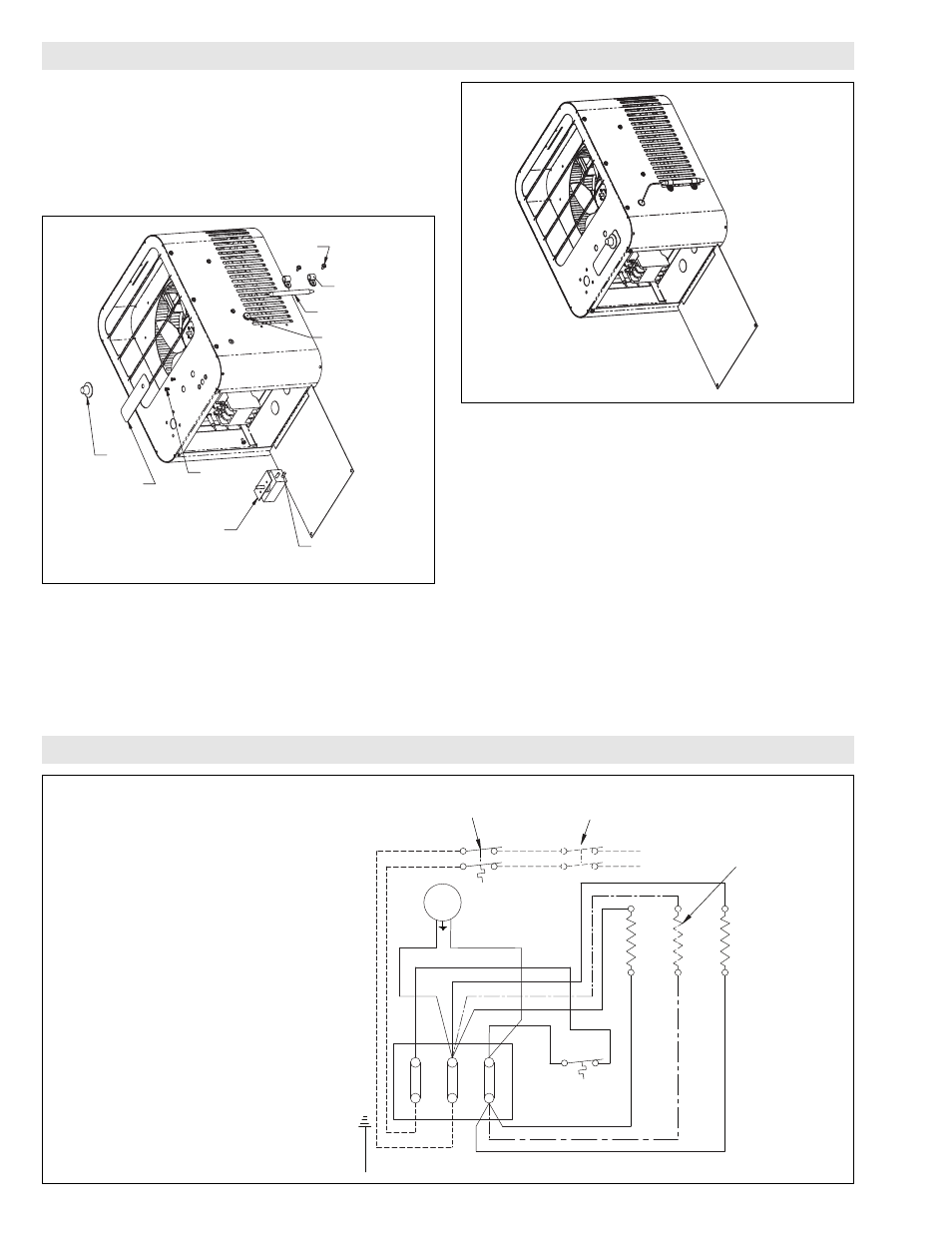
INSTALLATION (cont’d.)
Step 2 (Figure 2)
1. Remove (2) screws on cover and open cover.
2. Feed thermostat capillary (be careful not to kink or make any
sharp bends) out through the hole made in step 1.
3. Mount body of thermostat to front of heater case using the (2)
6-32 flat head screws (not location of leadwires shown in illus-
tration). Attach new label and knob provided with TK kit.
Step 3 (Figure 3)
1. Attach thermostat bulb to case using the (2) clamps and
screws.
2. Make a slit in the rubber grommet and insert the grommet over
the capillary.
3. Install the grommet into the hole in the case.
Step 4
1. For TK-6 Thermostat kits, wire one blue lead of thermostat to
terminal block pole “L1” and the other blue lead to terminal
block pole “L2”. Connect incoming power wiring to the black
leads with wire nuts provided by others. See figure 4 for line
voltage thermostat. See figure 8 for control voltage thermostat.
For TK-5 thermostat kits with an internally provided control
circuit, remove white jumper wire on terminal block between
poles “C1” and “C2”. Connect blue wire of thermostat to pole
“C1” and black wire to “C2”. See figures 5, 6 or 7.
For TK-5 thermostat kits with an externally provided control
circuit, remove white jumper wire on terminal block between
poles “C2” and “C3”. Connect blue wire of thermostat to pole
“C2” and black wire to “C3”. See figure 7.
2. Inspect wiring to make sure it matches the appropriate wiring
diagram.
3. Close heater cover and reattach screws.
SHEET METAL
SCREW
CLAMP
THERMOSTAT
BULB
KNOB
LABEL FOR
THERMOSTAT
6-32 FLAT
HEAD
SCREW
THERMOSTAT
BODY
RUBBER
GROMMET
LEADWIRES
Figure 2
Figure 3
}
Motor
Blue
Blue
Optional Thermostat
Built in or field installed
Optional Disconnect Switch
Built in or field installed
Power
60 Hz
Elements
1Ø Element Wiring
(Omit for 2 Element
Heaters)
Cutout
Terminal
Block
T1
T3
T2
L1
L3
L2
Black
Black
Figure 4
208-277V 1Ø — 2.6 & 5 kW
WIRING DIAGRAMS