Line voltage wiring low voltage wiring – Crown Boiler BB100H User Manual
Page 20
18
19
Connecting BB100C to Type III MCBA Equipped boilers (Figure 7.4):
5)
Connect the boiler circulator hot to the red lead and neutral (white) in the Boiler’s J-Box.
a.
Connect the three way zone valve in the BB100I to the blue lead and neutral (white) in the boiler’s J-box. If
b.
the system has a single system circulator having a draw of less than 1.5A, the system circulator can be wired in
parallel with the zone valve (after reprogramming the MCBA per part G of this manual, the zone valve will be
powered during a call for heat). Otherwise, a relay or zoning panel must be used to operate the system pump.
The heating thermostat, or zoning panel boiler contacts, are connected to terminals 1&2 on the boiler.
c.
The BB100M/BB100C flow switch is connected to terminals 7&8 on the boiler. IWH thermostat contacts must
d.
be “dry”.
Connecting BB100C to Sola Equipped boilers (Figure 7.5):
6)
Connect the boiler circulator to the terminals marked “BLR Pump” in the boiler’s J-Box.
a.
Connect the three way zone valve in the BB100C to the terminals marked “DHW Pump” in the boiler’s J-Box.
b.
Connect the system circulator to the terminals marked “Sys Pump” in the boiler’s J-Box.
c.
Connect the heating thermostat, or zoning panel boiler contacts, to the “CH Stat” terminals on the left side of
d.
the boiler’s control compartment.
Connect the BB100C flow switch to the “DHW Stat” terminals on the left side of the boiler’s control
e.
compartment.
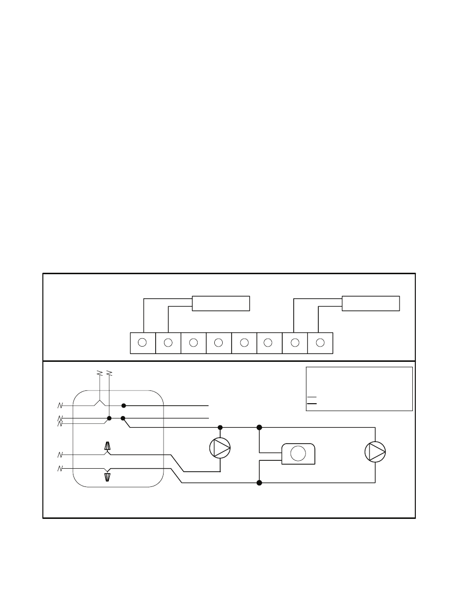
FIGURE 7.2: Wiring BB100I to Boiler equipped with Type III MCBA
Boiler
Circulator
BB100I 3-Way
Zone Valve
System Circulator
(Less Than 1.5 A )
BWC J-Box
L1
L2
BK - Black
WT- White
R - Red
BL - Blue
Line Voltage Factory Wiring
Line Voltage Field Wiring
Heating T-Stat
1
2
3
4
5
6
7
8
Low Voltage
Terminal Strip
BL
R
WT
WT
BK
DHW T-Stat
ZV
Line Voltage
Wiring
Low Voltage
Wiring