Temperature-pressure relief valve, Awarning, Warning “relief valve opening – Kenmore POWER MISER 153.320390 HT 30 GAL User Manual
Page 9: Installation instructions (cont’d)
Attention! The text in this document has been recognized automatically. To view the original document, you can use the "Original mode".
Installation Instructions (cont’d)
Temperature-Pressure
Relief Valve
AWARNING
At die tíme of manufocture thb ¥rater heater was provided with
a combination temperature-pressures relief valve certified by a
nationally recognized ^ng laboratory that maintains période
inspection of production of listed equipment or materials, as
meeting the requirements for Relief Vidves and Automatic Gas
Shutoff Devices for Hot Water Supply Systems, and the latest
edition of ANSI
Z21.22
and the code requirements of ASHE If
replaced, the valve must meet the requirements of local codes,
but not less than a combination temperature and pressure relief
valve certified as meeting the requirements for Relief Viilves and
Automatic Gas Shutoff Devices for Hot >^ter Supply Systems,
ANSI Z2I.22 by a nationally recognized testing laboratory that
maintains periodic inspection of induction of listed equipment
or materials.
The valve must be marked with a maximum set pressure not
to exceed the marked hydrostatic working pressure of the
water heater (ISO lbs./sq. in.) and a discharge capacity not
less than tíie water heater input rate as shown on the model
rating plate. (Electric heaters • watts divided by 1000 x 3415
equal BTU/Hr. rate.)
Your local jurisdictional authority while mandating the use of a
temperature-pressure relief valve complying with ANSI Z2I.22
a^ ASHE m^ require a valve model different from the one fur
nished with the water heater.
Compliance with such local requirements must be satisfied by
the installer or end user of the water heater with a locally pre
scribed tempeiatore-pressure relief valve installed in the desig
nated opening in the water heater in place of the fectory fur
nished rálve.
For safe operation of the water heater, the relief valve must not
be removed from №s designated opening or plugged.
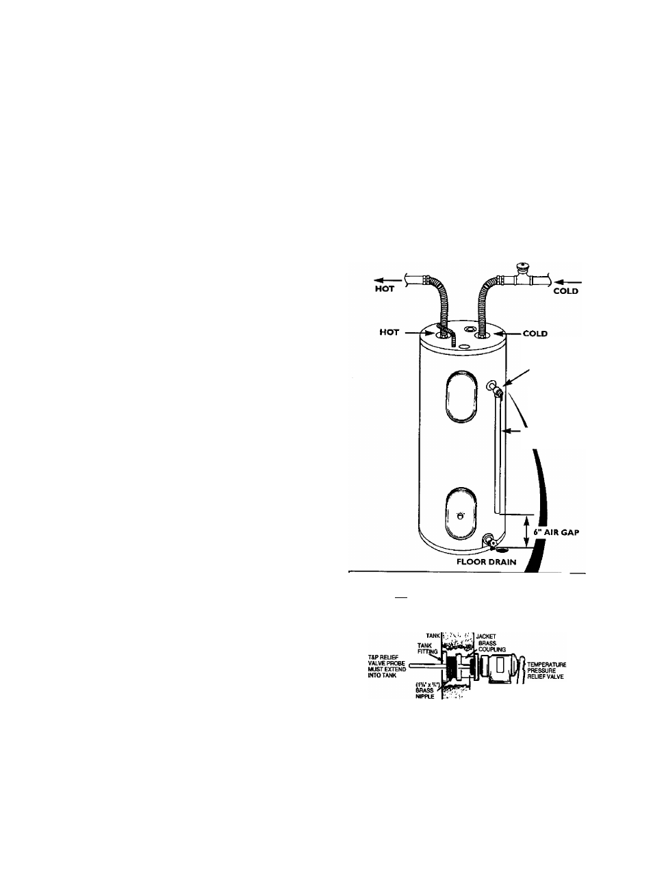
The temperature-pressure relief valve must be installed directly
into the fitting of the water heater designated for the relief valve.
Position the valve downward and provide tubing so that any dis
charge will exit only within 6 inches above, or at any distance
below the structural floor. Be certain that no contact is made
with any live electrical part The discharge opening must not be
blocked or reduced in size under any circumstances. Excessive
length, over 30 feet, or use of more than four elbows can cause
restriction and reduce the discharge capacity of the valve.
No valve or other obstruction is to be placed between the relief
valve and the tank. Do not connect tubing directly to discharge
drain unless a 6" air gap is provided. To prevent bodily injury,
hazard to life, or property damage, the relief valve must be
allowed to discharge water in quantities should circumstances
demand. If the discharge pipe is not connected to a drain or
other suitable means, the water flow may cause property
damage.
The Dischaige Pipe;
Must not be smaller in size than the outlet pipe size of the
valve, or have any reducing couplings or other restrictions.
Must not be plu¿¡ed or blocked.
Must be of material listed for hot water distribution.
Must be installed so as to allow complete drains of both
the temperature-pressure relief valve, and the discharge
pipe.
Must terminate at an adequate drain.
Must not have any valve between the relief valve and tank.
AWARNING
The temperature-pressure relief valve must be manually
operated at least once a year. Caution should be taken to
ensure that (I) no one is in front of or around the outlet
of the temperature-pressure relief valve discharge line,
3nd (2) the water manually discharged will not cause any
bodily injury or property damage because the water may
be extremely hot.
If after manually operating the valve, it fails to completely
reset and continues to release water, immediately, close
^e cold water inlet to the water heater, follow the drain
ing instructions, and replace the temperature-pressure
relief valve with a new one.
TEMPERATURE-
PRESSURE
RELIEF VALVE
DISCHARGE
PIPE
(Do not cap or plug)
WARNING “RELIEF VALVE OPENING
TtU
anttf
healer
is
provided
eilh
a
ombinatoi
Temperalute-Pressure
Relief
Valve
lisled
as
comnlviio
rtph
Bn
sBndaid
tor
H^Valws
and
Automatic
SasShuliin
Devices
for
Hot
Water
Siipply
Systems.
ANSai22
and ttw
oo
G
b
fBQidrBAMrtt o( ASluE.
Your lOGBlJulsdboiW M Mliile monOaling Ihe usa ol a Temperature-Pressura Raief Va)w cotruNra
wiftAHS221.22 and ASMS, may requirea valw model dtffefflni from
ComplancB witi suett local loqunfnerts must be salislied by the irisbilof or end user of the water Iwier w№
a locally prescribed Temparalura'Pressi.ire ReHer Vahra installed in vw designated opening in the water
T4P
"SHANK
LENGTH
• If a short shank (less than 2’) temperatufa-pressure relief valve is lo be installed
(as shown), a nipple and coupling must be used.
* If a long shank (2* or longer) is to be InstaBed, do not uee the nippia and coupJng.
Inslal
Tempeoture-Pressure
protedm
equqiment
required
by
local
codes,
but
not
less
than
a
corrtott-
bon
Temperalure-Prassura
Reliel
VaNe
cenitied
as
meeting
№e
requiremenls
I
qj
Fteliet
Valves
and
Aiaomabc Gas ShutofI Devices lor Hot-Water Supply Systems, MS Z2122 by a nationaly recognized lest*
ing
laboratory
that
mainiains
periotic
inspection
of
production
of
isted
equipTwit
o*
materials.
The
vahn
net be oriented, piovidsd weh tubing, or otherwise nstalsd
so
that dscharge can exit only wilhn
$
inches
ebove, or at any distance below the structural №or, and cannot contact any live elecin^ pen'
For safe operation of the water heater, the Relief Valve must
M
be removed or plugged.
See
manual
heading
-
'Temperature-Pressure
R^ef
Valve*
tor
installatior^
and
rnaintenance
of
Reliel
Valve, discharge pipe and other safety precautions.