Installation instructions (cont’d), Wiring diagrams – Kenmore POWER MISER 153.316555 User Manual
Page 13
Attention! The text in this document has been recognized automatically. To view the original document, you can use the "Original mode".
Installation Instructions (cont’d)
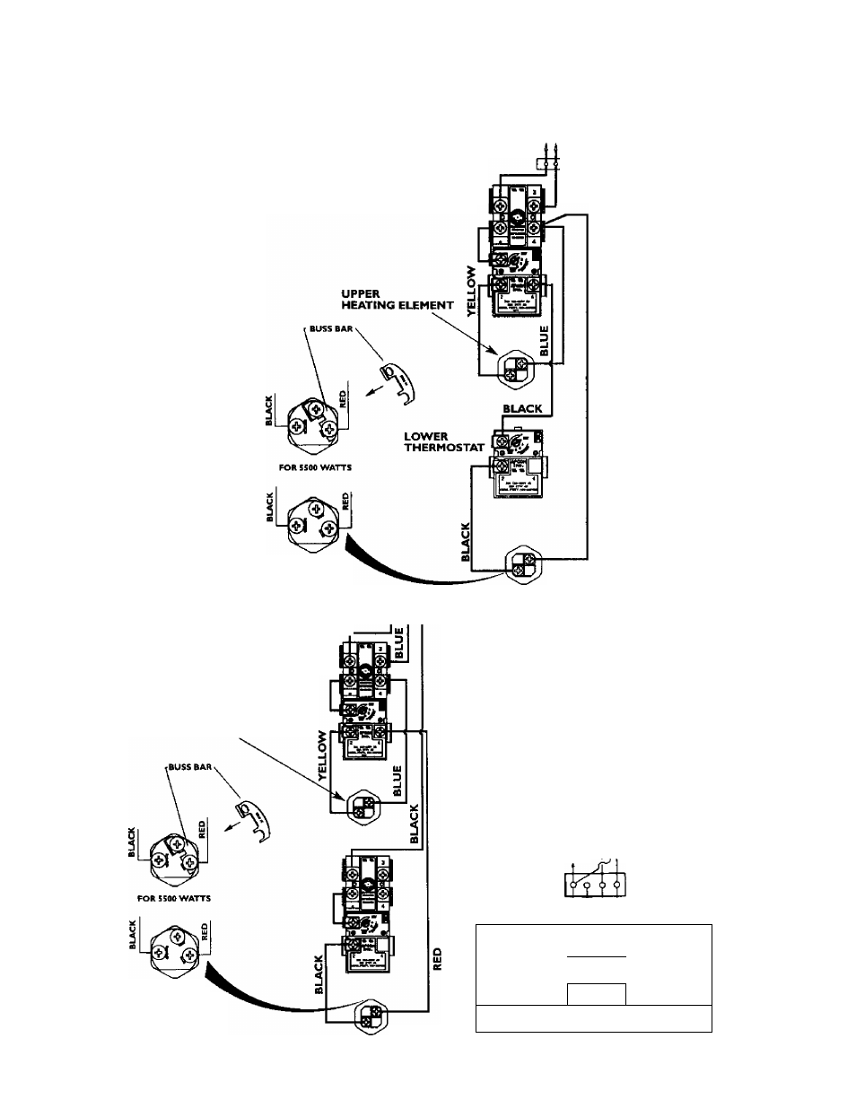
Wiring Diagrams
TO ELECTRIC
POWER SUPPLY
BLACK
STANDARD WIRING FOR
2 WIRE LEAD WATER HEATERS
NON-SIMULTANEOUS OPERATION
240 VOLT DOUBLE ELEMENT
UPPER
THERMOSTAT
RED
^ JUNCTION BOX
RED
FOR 3S00 WATTS
LOWER
HEATING ELEMENT
WIRING FOR 3 WIRE LEAD WATER YELLOW
HEATERS NON-SIMULTANEOUS
'
OPERATION 240 VOLT DOUBLE
ELEMENT
UPPER
HEATING ELEMENT
FOR J«00 WATTS
LOWER
THREE TYPES
OF FIELD
CONNECTIONS YOU
HAY HAVE
TIME CLOCK SWITCH
operates
bottom
element
only
to
electric
POWER SUPPLY LI LI L2 CLOCK SWITCH
JUNCTION BOX
TO TIME
yellow
I TBLUEP>-^CK
“OFF PEAK“ METER
OPERATES BOTTOM ELEMENT ONLY
TO ELECTRIC _ i _ i L t L 2 T O “OFF
POWER SUPPLY LI t ft PEAK“ METER
JUNCTION BOX
YELLOW
I
X
bl
U
e
I^I^CK
FOR TWO WIRE CONNECTION
POWER SUPPLY LI
—1
L2
JUNCTION BOX
yellow
! ^BLU^ BLACK
HEATING ELEMENT
*Note: Some Lower Hi-Temp Limit switches may have 4 terminals* Use only the 2 terminals on left.
13