Soldered copper installation, Fig.3, Using compression fittings, fig, 1 – Kenmore 625.3845 User Manual
Page 5: Installation steps a
Attention! The text in this document has been recognized automatically. To view the original document, you can use the "Original mode".
TYPICAL UNDERSINK INSTALLATIONS / TOOLS AND MATERIALS NEEDED
FIG. 2
TO SINK
FAUCET
HOT VCOLD,
shutoff valve
SOLDERED COPPER INSTALLATION
{OBSERVE FIG. 1 NOTES)
3/8” copper
J
/ pipe, as req'd
Q][-------------------------
90°ellJow (4)
adaptor,
3/6" NPT X sweat
(apply several wraps of
Teflon tape to threads)
- MATERIALS AND TOOLS NEEDED -
(see page 6)
FIG.3
THREADED INSTALLATION
(OBSERVE FIG, 1 NOTES)
TO SINK
FAUCET
union fitting
HOT
3/8” eltx)w (3)
3/8” street
elbow
apply several
wraps of Teflon
tape to all
threads
shutoff valve
' MATERIALS AND TOOLS NEEDED ■
(see page 7)
INSTALLATION STEPS
A,
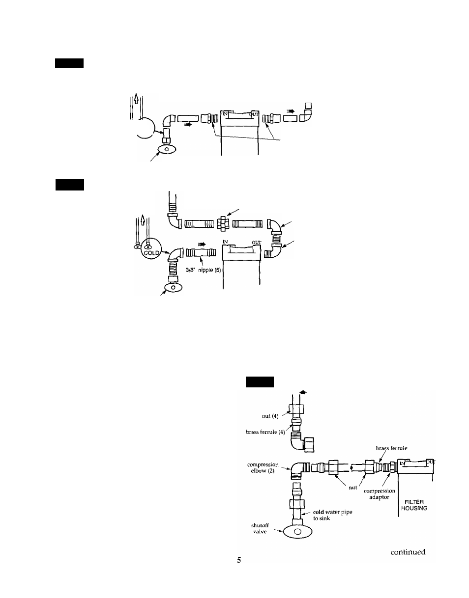
USING COMPRESSION FITTINGS, FIG, 1
Note:
If plumbing with flexible tubing, hang or sup
port the filter housing in some manner. Using the
mounting bracket (included) as shown in FIG. 1.
1. Apply several wraps of Teflon tape to the threads
of both compression adaptors.
2. CAREFULLY turn the compression adaptors into
the water filter head inlet and outlet and tighten. Do
not cross-thread and damage the threads. Do not
overtighten and crack the head.
3. CAUTION: Turn off the water supply to the sink
cold pipe. Open the sink cold faucet to relieve pres
sure in the pipe.
Note:
If the sink faucet is a single lever mixing type
also close the shutoff valve on the hot water side.
4. Use a tubing cutter to remove a section of the cold
water pipe (catch trapped water with a rag or tow
el), Remove all burrs and rough edges with the sand
paper or emery-cloth.
5. Place a nut and brass ferrule (from compression el
bow fittings) onto both pipe ends. Connect elbows to
the sink cold water pipe as shown below.
FIG. 4
TO SINK
COLD FAUCET