Figl – Kenmore 564.8815022 User Manual
Page 2
Attention! The text in this document has been recognized automatically. To view the original document, you can use the "Original mode".
Read and understand these instructions thoroughly before installing
beer dispenser.
ASSEMBLY
1.
Carton Inventory
Unpack aruJ inspect the parts. Make sure all items are present
and in good condition.
1 Draft arm assembly (Package includes 1 gasket for
draft arm and 1 washer for connection to keg tapper)
1 CO
2 regulator
1
CO
2
cylinder
1 Keg tapper (Sankey type)
1 Cleaning kit
1 Pressure tube
2 Hose clamps
2 Keg supports (wooden plates)
1 CO
2 cylinder retainer (spring)
1 Guard rail
1 Drip tray
4 Wheel casters
4 Hex head screws (5mm dia x 15mm long)
16 Machine screws (5mm dia x 12mm long)
8 Small screws (5mm dia x 10mm long)
2.
Install casters
a.
Empty the cabinet and then lay down the beer dispenser
sideways so that the door hinge side comes to the top. Be
careful not to cause dents or scratches on the cabinet.
Placing outer carton underneath the cabinet is
recommended.
b.
Install casters to the four bottom corners of the cabinet
with the four machine screws (5mm dia x 12mm long) for
each caster.
c.
Stand the cabinet upright.
3.
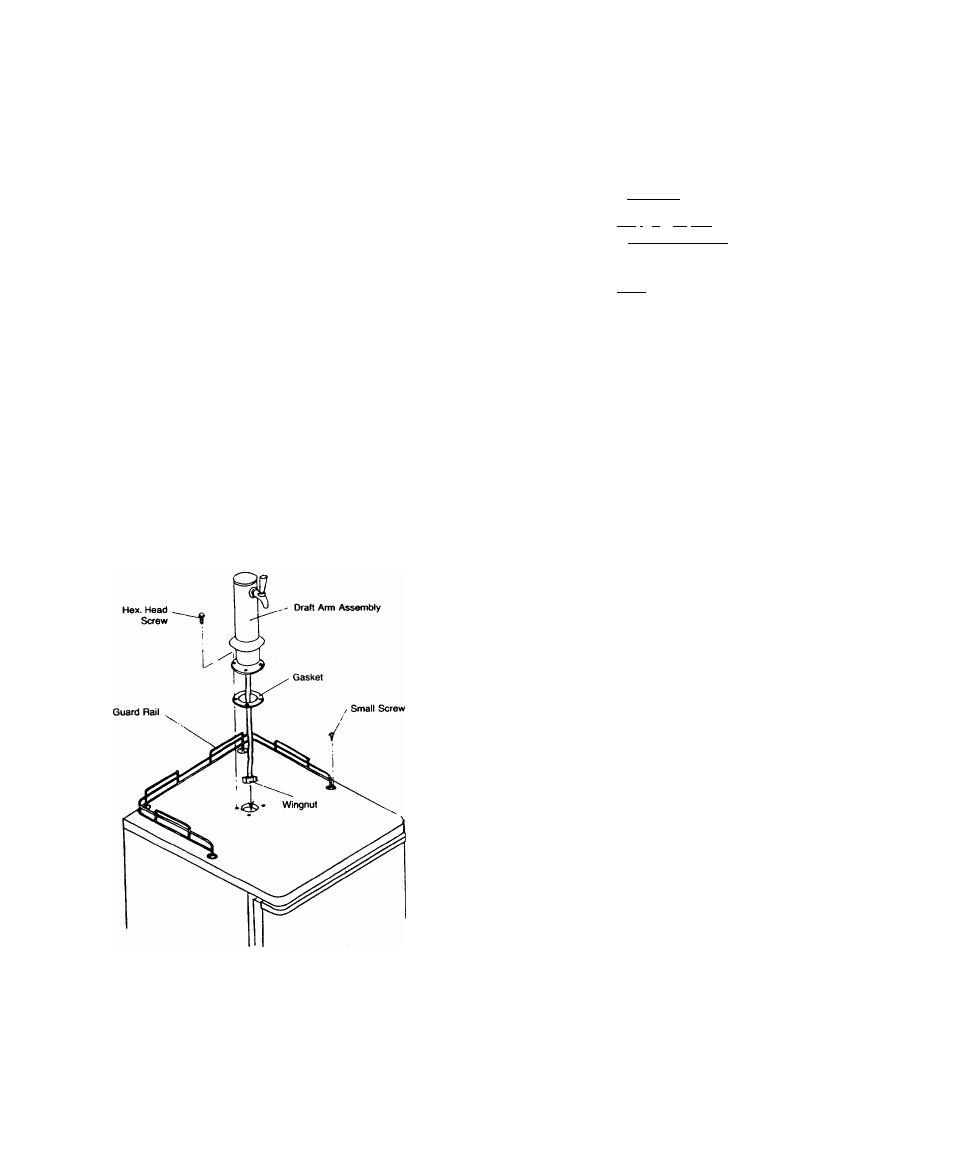
Install Draft Arm Assembly (See Fig. 1).
a.
Slide gasket over wingnut on bottom of draft arm assem
bly beer tube. Slide gasket up beer tube to draft arm base.
b.
Push wingnut and beer tube of draft arm assembly
through hole in top of cabinet until draft arm is resting on
cabinet top.
c.
Align holes in draft arm base with holes in gasket and pilot
holes in cabinet top, then secure draft arm to cabinet top
with four hex head screws (5mm dia x 15mm).
4.
Install Guard Rail (See Fig. 1).
a.
Place guard rail on cabinet top and secure guard rail with
eight small screws.
‘ ■ '
INSTALLATION
^ ’
1.
Install beer dispenser on strong, igYfjlutlO^'^ Avoid direct sun
light, hearsdOfcesanS moisture.
.
2.
Connect to42OVr60*Hz7-l9 Al IfirgrOOf¡31^
TXT
outlet. Do not
use extension cord. Use three-prong Dlua^adlh three-prong
grounded waTSuflefT“
.
.
WARNING: Unless the atSCiie'groundrng method
is
followed,
you are not protegtptL .against severe or lethal
shock in the event of a short circuit of an electrical
cpmponenLor-wirittg of beer dispenser.
TEMPERATURE CONTROL
1. Control is located on rear. First set the control at NORMAL pos
ition. Wait for 24 hours to check the temperature then adjust
temperature control, if needed.
DEFROST
1.
Beer dispenser will not require much defrosting since the
door opening is at a minimum. Defrost when % inch frost is
built up on the cold plate. The best time to defrost is when
the keg is changed. To defrost, set temperature control at
OFF
position and leave door open until ice melts. Defrost
water will accumulate at the bottom of interior cabinet
which can be absorbed with a sponge or towel. Do nofuse
heating
devices
or
sharp
objects
to
speed
defrosting
as this could damage cabinet iiner of cold plate.
Reset
temperature control after defrosting is completed.
INSTALLATION OF BEER SYSTEM
1. Installing CO
2 Cylinder and C02 Regulator
WARNING: COj GAS CAN BE DANGEROUS
Read front pages of “Draught Beer Facts” book in
cluded in your cleaning kit for safety precautions
before installaing the CO
2 cylinder.
Figl.
OPERATING INSTRUCTIONS FOR COj CYLINDERS
Do not operate valve control unless cylinder is completely
installed and connected.
TURN HANDWHEEL FULLY COUNTERCLOCKWISE
AS FAR AS IT WILL GO»
IMPORTANT: If valve is not fully opened the stem may not
seal properly against the upper packing washer and the
valve may leak. If leak occurs when fully opened, tighten
down packing nut urKler handwheel then open and dose
valve fully several times. Replacement packing washer
must be ordered directly from valve manufacturer whose
name is stamped on valve.
-2-