Installation instructions, Place cabinet in window, Install support bracket – FRIGIDAIRE FRA186MT2 User Manual
Page 4
Attention! The text in this document has been recognized automatically. To view the original document, you can use the "Original mode".
Installation Instructions
FIG.9 Top window filler
panel leg
Bottom window
filler panel leg
WINDOW FILLER
PANEL
FIG.10
TOP VIEW
AIRCONDITIONER
CABINET
PLASTIC
FRAME
T SECTION
'SIDE RETAINER
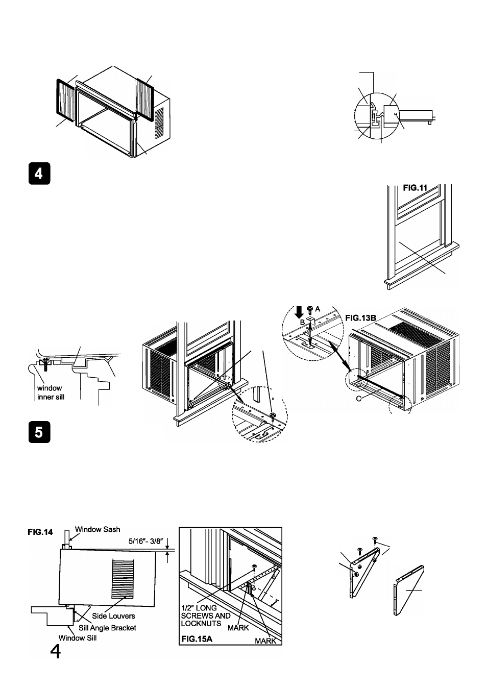
Place Cabinet in Window
WINDOW
FILLER
PANEL
LOCKING
SCREW HOLE
1. Open window and mark the center of window inner sill as shown (FIG. 11).
2. Place cabinet in window with cabinet bracket secureiy seated over edge of inner sili as shown
in FIG. 12. Bring window down temporarily behind top angie rail to hold cabinet in piace.
3. Shift cabinet left or right as needed to line up center of cabinet on center iine marked on inner
siil.
4. For wooden window: Fasten cabinet to window inner sill with two 1/2" iong hex head screws
into hoies (FIG.13A). (You may wish to pre-drill pilot holes.)
For Vinyl-Clad window: Place two safety locks into the holes located in the bottom of
the cabinet and drive two #10X1/4" pan-head Phillips locking screws through the safety locks
into the cabinet as shown (FIG.13B).
5. Remove protective strip from adhesive side of Bottom Rail Foam Seal.
Apply Seal over screws fastening bottom rail to window inner sill.
------
FIG.13A
Angle of cabinet
bracket securely seated
on edge of inner sill.
1/2" long
HEX-HEAD
SCREW
FIG.12
cabinet
Bracket
window
outer sill
Install Support Bracket
A. #10 X 1/4" pan-head Phillips screws
B. Safety Lock (Only for Vinly-Clad Window)
C. Bottom Rail Foam Seal
1. IHold each support bracket flush against outside of sill and tight to bottom of cabinet. Mark brackets at top level of
sill. Mark cabinet bottom at distance of sill width. See Fig. 15 A. Remove support brackets.
2. Attach sill angle brackets to support brackets at marked positions with flat head bolts and nuts. Hand tighten only
at this point. See Fig. 15B.
3. Insert 1/2" long bolts through appropriate holes in cabinet bottom given the sill width distance. Thread the bolts into
the slots of the support brackets. Tighten lock washer nuts onto bolts.
4. Adjust height of sill angle bracket so that bracket rests securely on edge of sill, and so that cabinet has the correct
5/8" to 3/8" downward tilt for proper water drainage (see Fig. 14). Tighten nuts securely.
FIG.15B
LEFT
LOCKNUT
SILL ANGLE
BRACKET
1/2" LONG SCREWS
'AND LOCKNUTS
RIGHT
FLAT HEAD BOLT
2 EACH REQ’D FOR EACH
SUPPORT BRACKET