Installation instructions (cont*d), Temperature-pressure relief valve, Temperature-pressure relief valve operation – Kenmore 153.337213 User Manual
Page 12: Relief valve opening
Attention! The text in this document has been recognized automatically. To view the original document, you can use the "Original mode".
Installation Instructions (cont*d)
Temperature-Pressure Relief Valve
AWARNiNG
At the time of manufacture this water heater was provided
vnth a combination temperature-pressures reilef valve certified
by a nationally recognized testing laboratory that maintains
periodic inspection of production of listed equipment or mate
rials, as meeting the requirements for Reiief Valves and
Automatic Gas Shutoff Devices for Hot Water Supply Systems,
and the latest edition of ANSI Z2I.22 and the code require
ments of ASME. If replaced, the valve must meet the require
ments of local codes, but not less than a combination tempera
ture and pressure relief valve certified as meeting the require
ments for Relief Valves and Automatic Gas Shutoff Devices for
Hot Water Supply Systems, ANSI Z2I.22 by a nationally recog
nized testing laboratory that maintains periodic inspection of
production of listed equipment or materials.
The valve must be marioed mth a maximum set pressure not
to exceed the marked hydrostatic working pressure of the
water heater (ISO Ibsfsq. in.) and a discharge capacity not less
than the water heater input rate as shown on die model rating
plate. (Electric heaters - watts divided by 1000 x 3415 equal
BTU/Hr. rate.)
Your local jurisdictional authority, while mandating the use of a
temperature-pressure relief valve complying with ANSI Z2I.22
and ASME, may require a valve model different from the one
furnished vidth tiie water heater.
Compliance with such local requirements must be satisfied by
the installer or end user of the water heater with a locally pre
scribed temperature-pressure relief valve installed In the desig
nated opening in the water heater in place of the fectory for-
nished valve.
For safe operation of the water heater, the relief valve must not
be removed from it^ designated opening or plugged.
The temperature-pressure relief valve must be installed directly
into the fitting of the water heater designated for the relief valve.
Position the valve downward and provide tubing so tiiat any dis
charge will exit only within 6 inches above, or at any distance
below the structural floor. Be certain that no contact is made
with any live electrical part The diKhatge opening must not be
blocked or reduced in size under any circumstances. Excessive
lengA, over 30 feet, or use of more than four elbows can cause
restriction and reduce the discharge capacity of the valve.
No valve or other obstruction is to be placed between the relief
vatrç and the tank. Do not connect tubing directly to discharge
drain unless a 6" air gap is provided. 1b prevent bodily injury, haz
ard to life, or property damage, the relief valve must be allowed
to discharge water in quantities should circumstances demand. If
the dischai^ pipe is not connected to a dr^n or other suitable
means, the water flow may cause property damage.
The Discharge Pipe:
* Must not be smaller in size than the outlet pipe size of the
valve, or have any reducing couplings or other restrictions.
* Must not be plumed or blocked.
> Must be of material listed for hot water distribution.
■ Must be installed so as to allow complete drainage of both
the temperature-pressure relief valve, and the discharge
pipe.
■ Must terminate at an adequate drain.
* Must not have any valve between the relief valve and tank.
AWARNING
The temperature-pressure relief valve must be manually
operated at least once a year. Caution should be taken to
ensure that (I) no one b in front of or around the outlet of
the temperaiure-pressure reilef valve discharge line, and (2)
the water manually discharged will not cause any bodily
injury or property damage because the water may be
extremely hot
If after manually operating the valve, it feib to ccmipletely
reset and continues to reiràse water, immediately dose the
cold water inlet to the water heater, follow the draining
instructions, and replace the temperature-pressure relief
valve with a new one.
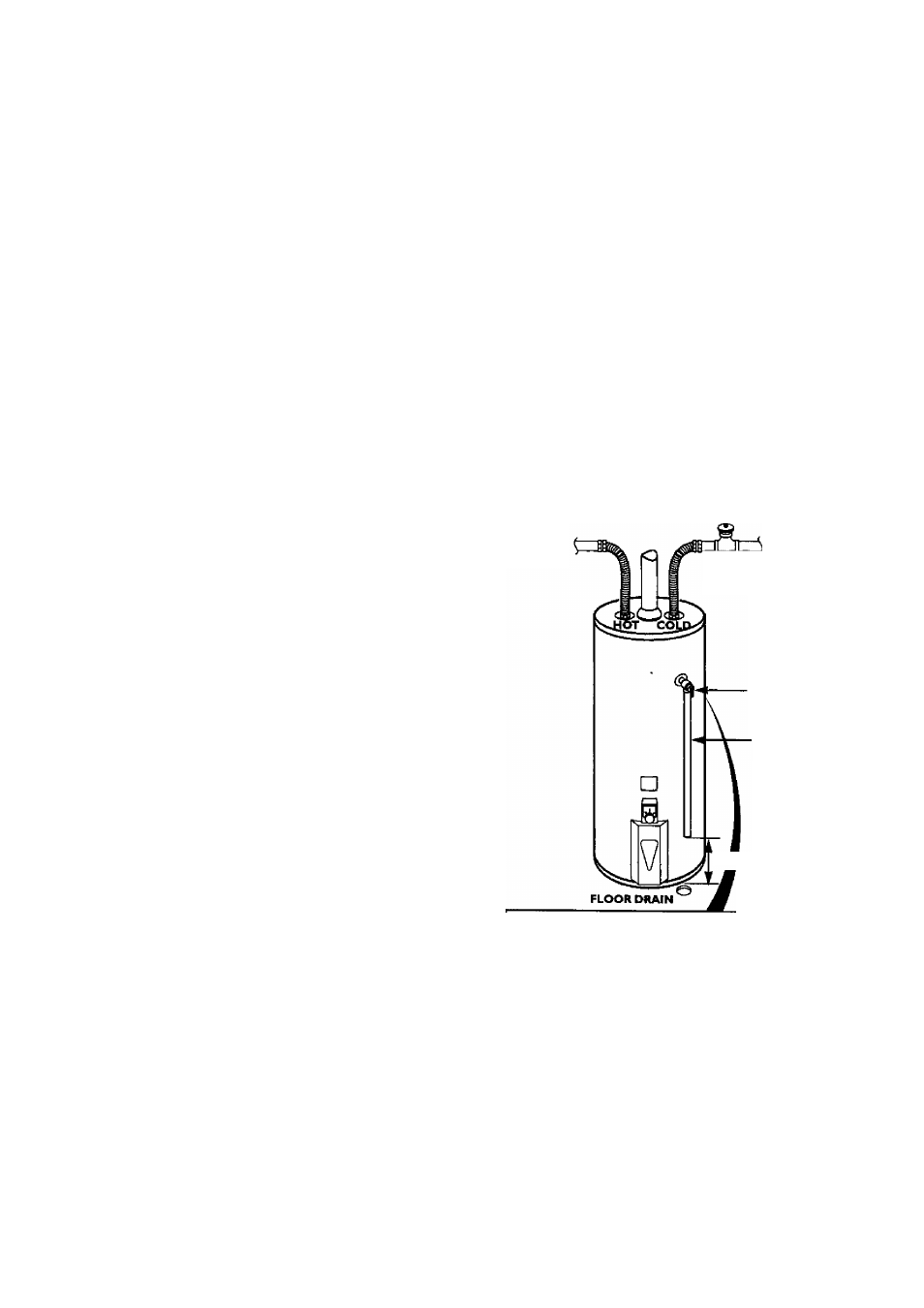
HOT
SHUTOFF COLD
VALVE
TEMPERATURE-
PRESSURE
REUEF VALVE
DISCHARGE PIPE
(Do not cap or plug)
i“AIR GAP
RELIEF VALVE OPENING
At the time of itnnufKture. this water heater was proved with a combination tem
perature-pressure reiief valve listed as complying with the standard ^ i^lief vaim and
automatic gas shut-ofF devices for hot water supply systems. ANSI
^ safe
operaciofl of the water heater, the reiief vaive must not be removed from its designated
point of instaílatíon or plugged.
Your local jurisdictional authority, while mandating the use of a temperature-pressure
relief i^ve compl)nng with W'fSI Z2I.22 and ASME, may require a valve model different
from the one furnished with the water heater.
Comf^iance with such local requirements must be satisfied by the installer or end user
of the water heater with a locally prescribed temperature-pressure rdi^ valve installed
in the designated opening In the water heater.
See manual heading -"Temperature-Pressure Relief Wives" for installation and mainte
nance of relief valve, discharge line, and other safety precautions.
12