Installation – Whirlpool 311435 User Manual
Page 3
Attention! The text in this document has been recognized automatically. To view the original document, you can use the "Original mode".
1. If local codes permit connection of the frame ground
ing conductor to the neutral (white wire),
connect the
green and white wire from the supply cable of the
appliance together and to the neutral (white) wire in
the junction box. Connect the remaining wires from
the supply cable, matching the colors, to the wires in
the junction box.
2. If local codes DO NOT permit frame grounding to the
neutral,
separate the white and green wires that
extend out of the end of the supply cable of the
appliance. Connect the white wire from the supply
cable to the neutral wire in the junction box.
Connect the black and red wire from the supply cable,
matching the colors, to the corresponding wires in the
junction box. The green wire MUST now be used to
ground the appliance in accordance with local electri
cal codes. Connect the green ground wire to a
grounded cold water pipe*or to the grounded lead in
the service panel
Do not ground to a gas supply pipe.
Dc not connect to electrical power supply until
appliance
is
permanently
grounded.
Connect
the
ground wire before turning on the power.
S e e F i g u r e
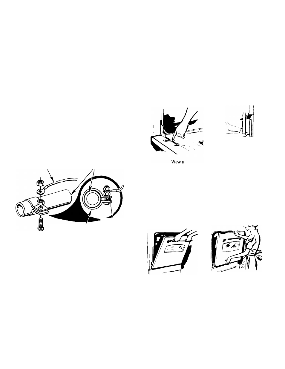
3. INSTALLATION
COPPER
GROUND WIRE
GROUNDED COLD
WATER PIPE
(REMOVE PAINT, ETC.
TIGHTEN
NUTS FIRMLY
GROUND CLAMP
(MUST BE TIGHT
ON PIPE)
FIGURE 2
’^Coici water pipe must have metal continuity to electrical
ground and not be interrupted by plastic, rubber or other
electrically insulating connectors (including water meter
or pump) without adding a jumper wire at these connec
tions.
CAUTION — If connecting to a four-wire electrical system
(MOBILE HOME) the appliance frame
MUST NOT
be
connected to the neutral wire of the four-wire electrical
system. Separate the white and green wires that extend
out af the end of the supply cable of the appliance.
Connect the white, red and black wires from the supply
cable, matching the colors, to the corresponding wires in
the junction box. Connect the green wire from the supply
cable to the ground wire in the junction box.
NOTE:
Before installing the oven in the cutout, it may be helpful
to remove the oven door. See details below.
Insert appliance into cut-out. Screws are provided for
fastening the front frame of the appliance to the cabinet.
The
mounting
holes
in
the
front
frame
of
appliance may be used as a template to locate the ap
pliance mounting screw holes.
CAUTION; For your personal safety, and to minimize
potentiai personai injury, this oven must be secureiy
fastened to the cabinet, using the four screws that are
provided.
Use caution when mounting oven in cutout so you do
not overtighten screws and cause porceiain chippage
or puncture oven cavity.
TO REMOVE OVEN
View
b
1. Open door fully.
2. Swing the 2 clips located on door in front of hinges so they
cross over the hinge slots (View a).
3. Close the oven door slowly until you feel it stop.
4. Lift up slightly allowing the bottom of the door to swing out.
(View b) Note that the top of the door must be tilted toward
the oven at this point to allow hing arms to swing free, if
appliance is so located that you cannot grasp both sides
of door you may grasp the door by handle (View c) and
follow same procedure outlined above.
TO REPLACE OVEN DOOR
View
c
View d
1. Grasp door by sides (View b) or by handle and align hinge
arms on door with TOP of slot in oven sides.
2. Tilt top of door toward the oven (View b) and allow door
to “ride” into position. A slight lifting and inward pressure
toward the bottom of the door will make sure it seats pro
perly. (View d).
3. Open door fully and swing the clips away from the slots
(View a).