A warning, A caution, L.p. gas conversion – Whirlpool 316002904 User Manual
Page 4
Attention! The text in this document has been recognized automatically. To view the original document, you can use the "Original mode".
8
If installing the range in a mobile
home, you MUST secure the range to the
floor. Any method of securing the range is
adequate as long as it conforms to the
standards listed in the Mobile Home
Installation Instructions, Panel A.
■ Place rack in oven.
Place level on rack, first
side to side; then front to
back. If range is not level,
adjust the leveling legs up or down until the
range is level.
Note: Oven must be level for satisfactory
baking conditions.
A WARNING
Fire Hazard
Do Not make connection too tight. The
regulator is die cast.
Overtightening may crack the regulator,
resulting in a gas leak and possible fire
or explosion.
All connections must be
wrenc h-tightened.
flexible connector
manual shutoff
valve
pressure regulator
10
.
1 /2" flare union adapters
Assemble the flexible connector from the
gas supply pipe to the pressure regulator
located in the bottom rear of range in this
order: shutoff valve, 1 /2“ flare union
adapter, flexible connector, 1 /2" flare union
adapter. Seal all openings in floor or wall
wherever range is installed.
11
b
Use pipe-joint compound made
for use with Natural and L.P, gas to seal all
gas connections. If flexible connectors are
used, be certain connector is not kinked.
12
■ B Open the shutoff valve in the gas
supply line. Wait a few minutes for gas to
move through the gas line.
A WARNING
Fire Hazard
Do Not use an open flame to test for
leaks from gas connections.
Checking for leaks with a flame may
result in a fire or explosion.
13.
Use a brush and liquid detergent
to test all gas connections for leaks. Bubbles
around connections will indicate a leak. If a
leak appears, shut off gas valve controls
and adjust connections. Then check
connections again.
NEVER TEST FOR GAS
LEAKS WITH A MATCH OR OTHER FLAME.
Clean all detergent solution from range.
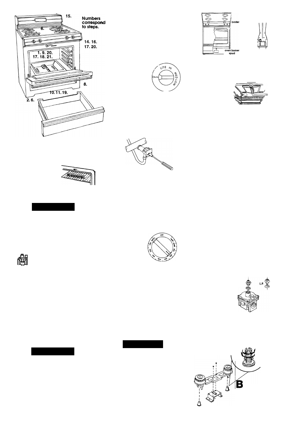
Panel C
Electronic Ignition System —
initial lighting and gas flame
adjustments.
Cooktop and oven burners use electronic
ignitors in place of standing pilots. When the
cooktop control knob is turned to "LITE"
position, the system creates a spark to light
the burner. This sparking continues until the
control knob is turned to the desired setting.
When the oven control is turned to the
desired setting, a glow bar heats up bright
orange and ignites the gas. No sparking
occurs and the glow bar remains on while
the burners operate.
14
B Check the
operation of the cooktop
burners. Push in and turn
each control knob to "LITE"
position. The flame should
___
light within 4 seconds.
Do Not leave the
knob in the “LITE” position after burner lights.
15
■ B After burner lights, turn
control knob to "HI" position. Check '
each cooktop burner for proper
flame. At the "HI" setting, the small
inner cone should have a very
distinct blue flame 1/2" long. The
outer cone is not as distinct as the inner
cone. No air adjustment can be made.
1
/
2
"
Push in and turn the
control knob to the "LITE" position
and then to the "LOW" position. The low
flame should be a minimum, steady, biue
flame. To adjust the burner, remove the
control knob and turn the adjustment screw
in the center of the valve stem. Check the
adjustment by turning the control knob from
"HI" to "LOW" several times. The burner is
properly adjusted when the low flame
remains steady and the burner does not go
out. Check each burner.
^
^9
Remove oven rack. Remove
I
B B oven screws at the rear of oven
bottom. Pull oven bottom rear up
and remove front of oven bottom from oven
front. Remove oven bottom. Remove baffle.
Check the operation of the oven burner.
If you have oven
selector and
temperature selector
control knobs;
Turn the
oven selector knob to
“Bake." Push in and turn
temperature control knob
to 300“F.
The oven burner should light in 50
to 60 seconds. This delay is normal.
The oven
safety valve requires a certain time before it
will open and allow gas to flow.
/”//■ ■/
l~ll~l3uP:
OO '-'O D
Ô©©©©©©
If you have electronic controls:
Push "BAKE"
button. 'L°F will appear in the display. Turn
Set knob until 350° appears in the display.
The oven burner should light in 50 to 60
seconds. This delay is normal.
The oven
safety valve requires a certain time before it
will open and allow gas to flow.
A CAUTION
Product Damage
• Do Not insert any object into the
openings of the protective shield that
surrounds the ignitor.
• Do Not clean the area.
Failure to follow these instructions could
result in product damage.
18
Check the oven
burner for proper flame. This flame
should have a 1" long, inner cone
of bluish-green, with an outer
mantle of dark blue, and should be
clean and soft in character. No
yellow tips, blowing or lifting of flame should
occur.
lock screw
air shutter
orifice
hood
19.
If oven flame needs to be adjusted, locate
the air shutter near the center rear of the
range. Loosen screw and adjust the air
shutter until the proper flame appears.
Tighten screw.
_____ „
^
20
Check
the operation of
the oven broil
burner.
If you have oven
selector and temperature selector control
knobs:
Turn the oven selector knob to
"BROIL". Push in and turn the oven
temperature selector knob to "BROIL".
The
oven broil burner should light in 50 to 60
seconds. This delay is normal.
The oven
safety valve requires a certain time before it
will open and allow gas to flow.
If you have electronic controls:
Push the
"BROIL" button. "_°F will appear in the
display. Turn the TIME/TEMP set knob one
click and "LO" will appear in the display. The
"BROIL" indicator light will come on when the
oven turns on.
The oven broil burner should
light in 50 to 60 seconds. This delay is
normal.
The oven safety valve requires a
certain time before it will open and allow
gas to flow.
21
■ B
If the broiler flame needs
adjustment:
1. Loosen the lock screw on the air shutter
located at the rear of the broil burner.
2.
Adjust the air shutter as needed. The
flame should have a 1" long inner cone
of bluish-green with an outer mantle of
dark blue. The flame also should be clean
and soft in character with no blowing or
lifting of flame. Tighten the lock screw.
Replace burner baffle, oven
bottom and racks.
To get the most efficient use from
your new range, read your Use
and Care Guide. Keep Installation
Instructions and Guide close to
range for easy reference.
L.P. gas conversion
Converting to L.P. gas should be done
by
a
qualified installer.
Natural
Pressure
regulator:
Remove storage
drawer and oven
rack. Remove oven
bottom, see Step 17.
Regulator is located
in lower right-hand
rear corner of range.
Use a wrench to unscrew the cap from the
top by turning counterclockwise. Turn the
cap over so the hole end is up. Replace the
cap and gasket on the regulator. DO NOT
REMOVE THE PRESSURE REGULATOR.
Nat. Gas
Increase gas
increase flame size
(Pre-set at factory
tor natural gas)
Pin
Spud
L.P. Gas
decrease gas
decrease
flame size
Cooktop
burners:
Turn the
orifice hoods down
snug onto pins
(approximately 2 to
2-1/2 turns). DO NOT
OVERTIGHTEN. The burner flames will not
be properly adjusted if this conversion is
not made.