For countertops with a backsplash, A warning, To prevent tipping, install the anti-tip bracket – Whirlpool SS373PEX1 User Manual
Page 5: A caution, Floor damage, Fire hazard, Ail connections must be wrench- tightened
Attention! The text in this document has been recognized automatically. To view the original document, you can use the "Original mode".
rear wall
transition
3/4" min.,
7/8" max.
Without
backsplash
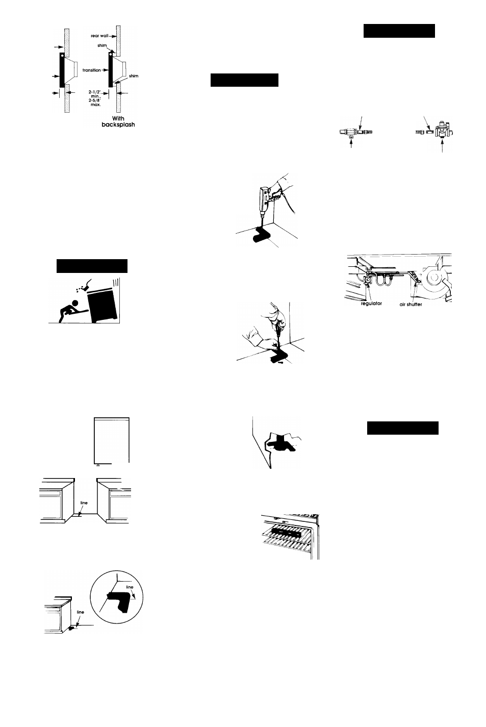
For countertops with a backsplash,
the distance from the rear wall to the
gasket must be at least 2-1/2";
2-5/8“ maximum.
Attach wall duct to range fan exhaust
with wall duct directed toward rear of
range.
Secure wall/floor duct plate to wall
duct using screws supplied.
8a.
For floor or left side venting: Follow
instructions supplied with floor vent kit
or left side vent kit.
A WARNING
To prevent tipping, install the anti-tip
bracket.
Save these Installation Instructions.
If range is moved to a new location,
the anti-tip bracket must be
removed and reinstalled in the new
location.
One anti-tip bracket must be installed,
• Measure the
distance from
the center of the
leveling leg to
the turthest point
that extends
trom the back of
the range.
leveling leg —►*
• Mark on the floor the distance just
measured trom the rear of the cabinet
opening or wall where the range will be
installed. Additional space may be
needed for gas line located behind the
range.
• Place one end of the anti-tip
bracket on the floor against the
cabinet side so that the inside edge
of the bracket is aligned with the line
drawn.
10
.
Use a pencil to mark the two mounting
screw hole locations on the anti-tip
bracket. Remove bracket from
position.
A CAUTION
Floor Damage
• Contact a qualified floor covering
installer for the best procedure to drill
mounting holes through your type of
floor covering.
> Before moving range across floor,
check that range is on shipping base
or slide range onto cardboard or
hardboard.
Failure to follow these instructions may
result in damage to floor covering.
1 1
.
cabinet
wall
To mount anti
tip bracket to
wood floor, drill
a 3/32" hole at
each mounting
screw location.
To mount anti-tip bracket to concrete or
ceramic floor, use a masonry drill bit to
drill 3/16" holes at eaoh mounting
screw location. Tap plastic anchors into
mounting holes in floor with hammer.
12
.
Line up holes in
anti-tip bracket
with holes in
floor. Use the
sorews provided
to fasten the
anti-tip bracket
to floor.
13
Move range close to final position.
Remove the shipping base, cardboard
or hardboard from under the range.
Plug power supply cord into grounded
outlet.
14.
Carefully move range
into final position.
Remove storage
drawer or look
underneath range. (A
flashlight may be needed.) Check that
the rear leveling leg is engaged in the
anti-tip bracket. If leveling leg is not
properly engaged, remove and
reposition the bracket to insure that the
leveling leg fits properly in the bracket.
15.
Place rack in oven. Place
level on rack, first side to
side; then front to back. If range
is not level, pull the range forward until
the rear leveling leg is removed from the
bracket. Adjust the legs up or down
until range is level. Push range back
into position. Check that rear leveling
leg is engaged in bracket.
Note: Oven must be level for
satisfactory baking oonditions.
16
Connect ductwork to range. Check
that power supply cord is not interfering
with duct work.
A WARNING
Fire Hazard
Do Not make connection too tight.
The regulator is die cast.
Overtightening may crack the
regulator, resulting in a gas leak
and possible fire or expiosion.
Ail connections must be wrench-
tightened.
1/2" nipple ,,
...
,
1/2" close nipple
flexible connector
\ /
1/2" adapter 1/2" adapter
manual
shutoff valve
pressure regulator
1 7
.
Remove the storage drawer by lifting
slightly and pulling out of range.
Remove the regulator plug and
assemble the flexible connector from
the gas supply to the pressure regulator
in order: manual shutoff valve, 1/2"
nipple, 1/2" adapter, flexible connector,
1/2" adapter, and 1/2" close nipple.
1 8
.
Pipe-joint compound made for use with
NATURAL and L.P. gas must be used to
seal all gas connections. Check that
the shutoff valve is open between the
regulator and gas valves. If flexible
connectors are used, be certain
connectors are not kinked.
19.
Open shutoff valve in the gas supply
line. Wait a few minutes for gas to
move through the gas line.
A WARNING
Fire Hazard
Do Not use an open fiame to test for
ieaks from gas connections.
Checking for leaks with a flame may
result in a fire or explosion.
20
.
Use a brush and liquid detergent to test
all gas connections for leaks. Bubbles
around connections will indicate a leak.
If a leak appears, shut ott gas valve
controls and adjust connections. Then
check connections again,
NEVER TEST
FOR GAS LEAKS WITH A MATCH OR
OTHER FLAME. Clean all detergent
solution from range.
21
Turn fan to "HI" to check that venting
gasket for rear wall or floor venting
properly seals wall/floor duct plate to
wall/floor transition. If range does not
seal properly, contact a service
technician. Replace storage drawer,
22
.
Install grill and surface burner modules.
Note: If there is a cabinet on only one
side, the anti-tip bracket must be
installed against the cabinet.
Panel D