Crestron c2n-tfm fm radio tuner, C2n-tfm ports, Am radio (rj-45) – Crestron electronic C2N-TFM User Manual
Page 9: Audio out l, r, Fm ant, G (chassis ground)
Crestron C2N-TFM
FM Radio Tuner
Operations Guide - DOC. 6233A
FM Radio Tuner: C2N-TFM
• 5
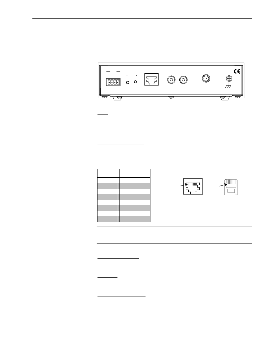
C2N-TFM Ports
All connections to the C2N-TFM, except headphones, are made through the ports on
the rear panel. Refer to the illustrations and descriptions, which follow.
C2N-TFM Ports
ANT
FM
G
USA
E L E C T R O N I C S I N C . , R O C K L E I G H , N J 0 7 6 4 7
CRESTRON
R
L
24 Y Z G
NET
SETUP
AM RADIO
AUDIO OUT
NET
This 4-pin mini-terminal block connector is used to connect the C2N-TFM module
to the Cresnet system. Data and power for the C2N-TFM are provided via the
connection. Refer to “Network Wiring” on page 8.
AM RADIO (RJ-45)
The RJ-45 AM RADIO port provides CAT5 interface (up to 500 feet) to the
companion Crestron C2N-TAMWX AM/Weather Tuner. Wiring for the connector is
shown in the following diagrams.
PIN #
SIGNAL
1 +24V
2
+24V
3 COM+
4
Audio+
5 Audio-
6
COM-
7 Ground
8
Ground
NOTE: This connector is to be used only to provide interface to Crestron products
specifically designed to work with this unit. It cannot be used for connections to
Cresnet or Crestron audio distribution devices.
AUDIO OUT L, R
These two RCA connectors provide line level stereo output for local amplifiers.
FM ANT
This Type F coaxial connector is for an FM antenna cable (not supplied).
G (Chassis Ground)
Use this chassis screw to ground the unit to the amplifier and audio source common
grounds.
8-PIN, RJ-45 PINOUT
CONNECTOR
(TAB FACING AWAY)
RECEPTACLE, REAR VIEW
(TAB POSITION DOWN)
Pin 1
Pin 1