220700 p3.pdf, Parts list for humidifier – Braeburn 220750 User Manual
Page 3
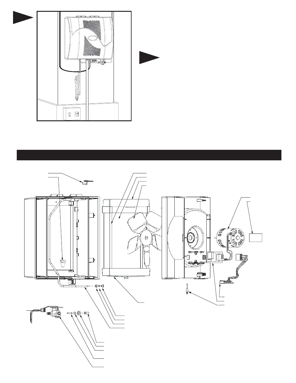
229237 MOTOR
NAMEPLATE
NOZZLE
SPOUT
PAD RAIL
229019 EVAPORATOR PAD
DISTRIBUTOR TROUGH
229247 FAN BLADE
ORIFICE - YELLOW
COMPRESSION SLEEVE (PLASTIC)
COMPRESSION NUT
DISTRIBUTOR TUBE
INSERT FOR PLASTIC TUBING
COMPRESSION NUT
COMPRESSION SLEEVE (BRASS) OR
COMPRESSION SLEEVE (PLASTIC)
229004 STRAINER SCREEN
SOLENOID & HARNESS
ASSEMBLY
DRAIN PAN
HARNESS - BOARD
229238 RELAY ASS'Y
POWER SUPPLY CORD
PARTS LIST FOR HUMIDIFIER
Turn on water supply and plug in power cord to check operation of
humidifier. Set humidistat to a demand setting. With the furnace off, the
solenoid valve should be closed and the humidifier fan not running. Start
the furnace, the solenoid valve should open and the humidifier fan run
when the blower or burner circuit is energized. Check flow of water through
distributor trough and evaporator pad. The standard yellow orifice will
supply approximately 3.5 GPH of water at a line water pressure of 60 psi.
Leave humidistat set at the recommended setting.
Replace evaporator pad assembly and humidifier cover. Insert low
voltage six connector wiring harness from cover into chassis solenoid
harness.
6
8
CIRCUIT DESCRIPTION
The humidifier is connected to the 120 volt AC circuit through a control
relay. The secondary coil of an isolation transformer, a diode and resistor
supply 24 volts for the control circuit which also includes the humidistat and
relay coil. When the control circuit is completed by the humidistat, the relay
closes, supplying 120 volts to the fan motor and 24 volts to the
solenoid valve.
7