220700 p2.pdf, Instructions for wiring humidifier, Figure 5a – Braeburn 220750 User Manual
Page 2: Figure 5b, Figure 5d, Figure 5e
5
FIGURE 5A
ACC
EAC
HOT
FURNACE
OR FAN
CONTROL
120 VAC
FURNACE
CONTROL
FIELD SUPPLIED
RECEPT & SWITCH
C
HUMIDIFIER
RED
POWER TO HUMIDISTAT
YELLOW
CONTROL
NOTE: Red wires are for humidistat power if required.
DO NOT CONNECT RED WIRES TO ANOTHER POWER
SOURCE OR ONE ANOTHER. DOING SO WILL VOID WARRANTY.
CAP OFF -
DO NOT CONNECT
TOGETHER
HUMIDISTAT
FIGURE 5B
HOT
MANUAL HUMIDISTAT
120 VAC WITH CURRENT
SENSING RELAY
FIELD SUPPLIED
RECEPT & SWITCH
C
HUMIDIFIER
RED
POWER TO HUMIDISTAT
YELLOW
NOTE: Red wires are for humidistat power if required.
DO NOT CONNECT RED WIRES TO ANOTHER POWER
SOURCE OR ONE ANOTHER. DOING SO WILL VOID WARRANTY.
NOTE: Yellow wires are for Humidistat Control. DO NOT APPLY
VOLTAGE TO YELLOW WIRES. DOING SO WILL VOID WARRANTY.
CURRENT
SENSING
RELAY
SINGLE OR
MULTI-SPEED FAN
C
HI
LO
CAP OFF -
DO NOT CONNECT
TOGETHER
HUMIDISTAT
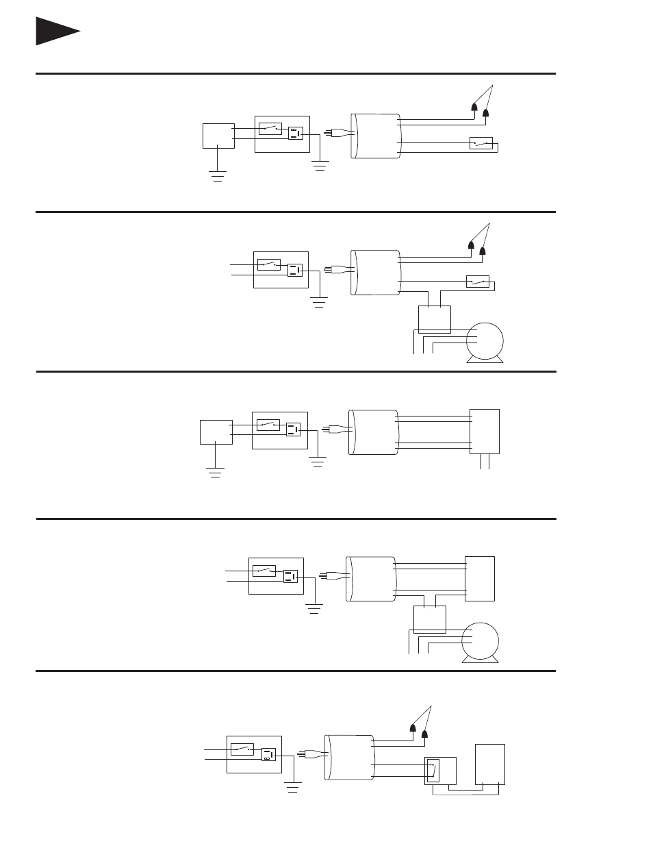
INSTRUCTIONS FOR WIRING HUMIDIFIER
On furnaces with output terminals ACC, or
EAC check output voltage to determine
that terminals are 115V. Connect on-off
switch in series with the hot wire.
On furnaces where it is desirable to use a
current sensing relay, the humidifier may
be wired from a continuous 115 volt
power source. Install the on/off switch in
series with the hot or black wire. Install
the Braeburn
®
229050 Current Sensing
Relay in series with the humidistat circuit.
The Current Sensing Relay will detect
furnace operation and supply power to
the humidifier accordingly.
FIGURE 5C
ACC
EAC
HOT
DIGITAL HUMIDISTAT
120 VAC WITH CONTROL FROM
FURNACE BOARD
FURNACE
OR FAN
CONTROL
120 VAC
FURNACE
CONTROL
FIELD SUPPLIED
RECEPT & SWITCH
C
HUMIDIFIER
RED
POWER TO HUMIDISTAT
YELLOW
CONTROL
ACN
ACL
HUM
HUM
TO OUTDOOR
SENSOR
HUMIDISTAT
NOTE: Red wires are for humidistat power.
DO NOT CONNECT RED WIRES TO ANOTHER POWER
SOURCE OR ONE ANOTHER. DOING SO WILL VOID WARRANTY.
FIGURE 5D
HOT
DIGITAL HUMIDISTAT
120 VAC WITH CURRENT
SENSING RELAY
FIELD SUPPLIED
RECEPT & SWITCH
C
HUMIDIFIER
RED
POWER TO HUMIDISTAT
YELLOW
ACN
ACL
HUM
HUM
HUMIDISTAT
NOTE: Red wires are for humidistat power.
DO NOT CONNECT RED WIRES TO ANOTHER POWER
SOURCE OR ONE ANOTHER. DOING SO WILL VOID WARRANTY.
NOTE: Yellow wires are for Humidistat Control. DO NOT APPLY
VOLTAGE TO YELLOW WIRES. DOING SO WILL VOID WARRANTY.
CURRENT
SENSING
RELAY
SINGLE OR
MULTI-SPEED FAN
C
HI
LO
FIGURE 5E
BRAEBURN
®
HUMIDITY
CONTROL THERMOSTAT
RED
YELLOW
C
BRAEBURN
HUMIDITY CONTROL
THERMOSTAT
NOTE: Red wires must be capped off. DO NOT
CONNECT TOGETHER. DOING SO WILL VOID WARRANTY.
ISOLATION
RELAY
RED
CAP OFF -
DO NOT CONNECT
TOGETHER
YELLOW
HOT
FIELD SUPPLIED
RECEPT & SWITCH
C
HUMIDIFIER
H
On systems where it is desirable to control
humidity levels in the conditioned space, a
Braeburn humidity controlling thermostat
may be used. Install a 24 VAC 1 Amp
minimum isolation relay as shown in
Figure 5E.
NOTE: Yellow wires are for Humidistat Control. DO NOT APPLY
VOLTAGE TO YELLOW WIRES. DOING SO WILL VOID WARRANTY.
NOTE: ALL WIRING SHOULD COMPLY WITH LOCAL ELECTRICAL CODES.
NOTE: Yellow wires are for Humidistat Control. DO NOT APPLY
VOLTAGE TO YELLOW WIRES. DOING SO WILL VOID WARRANTY.
MANUAL HUMIDISTAT
120 VAC WITH CONTROL
FROM FURNACE BOARD
On furnaces with output terminals ACC, or
EAC check output voltage to determine
that terminals are 115V. Connect on-off
switch in series with the hot wire.
On furnaces where it is desirable to use a
current sensing relay, the humidifier may
be wired from a continuous 115 volt
power source. Install the on/off switch in
series with the hot or black wire. Install
the Braeburn 229050 Current Sensing
Relay in series with the humidistat circuit.
The Current Sensing Relay will detect
furnace operation and supply power to
the humidifier accordingly.
NOTE:Yellow wires are for Humidistat Control. DO NOT APPLY
VOLTAGE TO YELLOW WIRES. DOING SO WILL VOID WARRANTY.