AXEON Fluid-O-Tech User Manual
Instruction manual, Wiring the motor to the power supply, Mounting the pump onto the motor
www.fluidotech.com
UNI ENI ISO 9001:2008
Cert. n°: 0363
INSTRUCTION
MANUAL
MANUAL - PO/MO/CO en – 07/12 Ed.
0
400
500
600
700
800
900
1000
1100
GPH l/h
1
2
20
3
4
5
6
7
8
9 10 11 12 13 14 15
40
60
80
100 120 140 160 180 200 220
0
150
200
250
PO500
PO600
PO700
PO800
PO900
PO1000
1450 RPM
PSI
BAR
16
PRESSURE
FLOW RATE
0
0
20
40
60
80
100
GPH l/h
450
375
300
225
150
75
0
PO400
PO350
PO300
PO250
PO200
PO150
PO100
PO070
0
20
40
60
80
100 120 140 160 180 200 220
1
2
3
4
5
6
7
8
9 10 11 12 13 14 15 16
1450 RPM
BAR
PSI
PRESSURE
FLOW RATE
0
0
1
2
3
4
5
6
7
8
9 10 11 12 13 14 15 16
10
20
30
40
50
60
l/h
GPH
70
0
20
40
60
80
100 120 140 160 180 200 220
1450 RPM
280
240
200
160
120
80
40
0
CO100
CO070
CO050
CO030
CO200
CO150
PSI
BAR
PRESSURE
FLOW RATE
l/h GPH
0
10
20
30
40
50
60
70
1725 RPM
280
240
200
160
120
80
40
0
CO100
CO070
CO050
CO030
CO200
CO150
0
20
40
60
80
100 120 140 160 180 200 220
BAR
1
PSI
8
7
6
5
4
3
2
11
10
9
12 13 14 15 16
0
PRESSURE
FLOW RATE
l/h GPH
PSI
BAR
0
0
20
40
60
80 100 120 140 160 180 200 220 240
1
2
3
4
5
6
7
8
9 10 11 12 13 14 15 16
600
500
160
140
120
100
80
60
40
20
400
300
200
100
0
0
1725 RPM
PO400
PO350
PO300
PO250
PO200
PO150
PO100
PO070
PRESSURE
FLOW RATE
PO500
PO600
PO700
PO800
PO900
PO1000
0
20
40
60
80
100 120 140 160 180 200 220
BAR
1725 RPM
120
160
200
240
280
320
360
GPH
l/h
600
800
1000
1200
1
PSI
8
7
6
5
4
3
2
11
10
9
12 13 14 15 16
0
PRESSURE
FLOW RATE
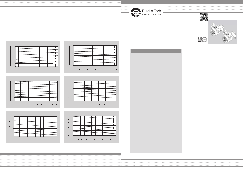
The above figures refer to measurements with by pass fully closed. Water temperature 20 °C (68 F). Figures of flow are averages.
POSITIVE DISPLACEMENT ROTARY VANE PUMPS:
PO 70-400, MO-CO 30-200 SERIES
The pump has to be installed exclusively by authorized
staff. Handle with care.
WARNING
For food applications the pumps (even when NSF
listed or WRAS approved) need to be sterilized by
circulating water at 80 °C (176 F) for at least 20
minutes. The water used for this operation must
not be reused, either during the sterilization or
later, but must be discharged.
It is recommended not pulling out the two protection
sponge caps placed on the inlet and outlet of the
pump before mounting the fittings and the pipes, to
avoid the incidental entrance of any solid extraneous
object which might damage the internal components
of the pump.The Fluid-o-Tech rotary vane pumps look
identical in their exterior aspect, within each range,
although the flow rates are different. For this reason,
when replacing just the pump, it is necessary to check
the model of the new pump. Changing the pump
with a model of different capacity may damage the
system, the motor and the pump itself.
If continuous operation is needed, the pump has to be
mounted in an airy space in order to dissipate
the heat produced from the motor.
The pump must be mounted horizontally.
To avoid noise and vibrations of mechanical parts,
it’s advisable to mount the motor on rubber shock-
absorbing supports.
The use of the dumper coupling kit for 48YZ frame
motors (3000300 for the parallel shaft type, 3000310
for the splined shaft type) is suggested in order to
avoid any missalignment between pump and motor.
WIRING THE MOTOR TO THE POWER SUPPLY
• The power supply must be consistent with the
electrical data stamped on the motor plate, with
particular regard to voltage and frequency.
The power supply needs to be switched off
during installation.
• The motor rotation must be clockwise (looking the
motor in front).
If operated counter-clockwise, the pump won’t
work. In case the rotation is counter-clockwise,
proceed according to the scheme generally
enclosed in the electrical wiring box.
• If the pump fails or some estraneous object enters
it, the pump-motor unit may stop or work in critical
conditions; for this reason the motor should have a
thermal protection to avoid overheating or a current
protection to avoid overloading.
MOUNTING THE PUMP ONTO THE MOTOR
a) Motor with clamp mounting (type 48YZ)
• Make sure the motor is unplugged
from the electric line
• Insert the clamp on the pump (shaft side)
• Clamp the pump to the motor by inserting the pump
shaft into the motor shaft and pushing it till it stops
• Turn the pump to the position desired
• Position the clamp in order to surmount the pump
and the motor rings
• Tighten the clamp using 1 - 1.5 Nm
torque maximum.
• Make sure that the clamp screw is tight enough
to prevent the rotation of the pump on the motor.
• Should the pump be noisy during the startup,
it is necessary to untighten the clamp screw,
reposition the pump and tighten again
the clamp screw.
LISTINGS
NSF Listed Pumps are marked PA/MA/CA instead of PO/
MO/CO, WRAS listed pumps are marked POW.
The “Compact” series pumps are not equipped with
weep holes, therefore the normal condensation may not
evaporate. In this case it is necessary coupling the pump
to a motor equipped with 4 90° holes in the coupling
area.
CERTIFICATIONS
The pump itself, without the motor, is not to be
considered as a machine, but only a component,
therefore the mark “CE” is not applicable. A conformity
declaration may be requested to state the essential
safety features (“Machinery Directive” 89/392/CEE). The
complete group is instead considered as a machine
ready to be used and it is supplied with the mark “CE”
that grants its conformity. Product in conformity with the
D.M. 174/2004.
Fluid-o-Tech Int’l Inc.
161 Atwater St.,
Plantsville CT (USA) 06479
Tel. +1 (860) 276-9270
Fax +1 (860) 620-0193
Fluid-o-Tech Int’l Inc. Japan
203, 2-17-19, Ebara, Shinagawa
Tokyo 142-0063, Japan
Tel. +81 (0) (3) 3783-9660
Fax +81 (0) (3) 3783-9661
Fluid-o-Tech Asia (Beijing) Co., Ltd
Jingwei Industrial Zone,
Beifang Huairou, Beijing, 101400, PRC
Tel. +86 (0) (10) 61684650
Fax +86 (0) (10) 61684651
Fluid-o-Tech srl
Via Leonardo da Vinci, 40
20094 Corsico, Milano, Italy
Tel. +39 02 8917071
Fax +39 02 89170799
Fluid-o-Tech reserves the right to alter the specifications indicated in this catalogue at any time and without prior notice.
INSTALLATION
Find out more