AvMap ULTRA UX0EFS2XAM User Manual
Page 15
14
- User and Installation Manual
AvMap
Ultra EFIS
User and Installation Manual -
15
AvMap
Ultra EFIS
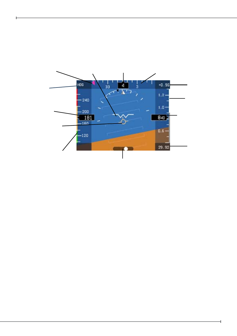
Figure 9
Air Speed
Indicator
Air Speed
Ranges
Trajectory
Vector
Altimeter
G-Meter
Kollsman
Window
(hPa or inHg)
Heading
Aircraft
Compass
Vertical Speed
Heading Bug
Side Slip Indicator
HDG
(Heading)
or COG (Course
over ground)
4.2 PFD mode
The PFD shows critical flight information like attitude, airspeed, altitude, as well as
other less critical flight variables like turn coordination, heading, load factor. A detailed
explanation of each instrument is given in Figure 9.
Attitude is displayed with a standard coloured artificial horizon. An aircraft symbol is
used to indicate the aircraft’s nose orientation.
A
trajectory vector is displayed with a circle and three lines; the trajectory vector
indicates the aircrafts real path with respect to the horizon and the aircraft’s nose.
Pitch
indicator
is displayed by markers that are horizontal with the horizon and are
equally divided with 10 degrees pitch of separation between the lines.
Roll indicator is displayed by markers of 10, 20, 30, 45 and 60 degrees of roll.
Indicated Air Speed (IAS) is shown in number representation as well as on
a vertical tape. The tape also displays four coloured lines for operating arcs;
white from the stall speed in dirty configuration (Vs0) to the maximum flap
extension speed (Vfe), green from the stall speed in clean configuration (Vs1) to
the maximum cruise speed (Vno), yellow from the maximum cruise speed (Vno) to
the never to exceed speed (Vne), and red from the never to exceed speed (Vne) and
higher.
Note: Aircraft specific V-Speed reference values can be entered in the “SETUP” menu
(see paragraph 4.4).
Note: In the “SETUP” menu select your preference unit for speeds: knots, kph, mph, m/s.