AAF International ArrestAll User Manual
Page 2
2
1.2 Foundations
The foundation must be level and adequate to support the collector ’s
operating weight including dust load, discharge devices, wind load if
applicable, plus any auxiliary equipment if applicable.
1.3 Space Requirements
Unit location will be determined by system design, space availability,
and access requirements. Access to the front of the unit is necessary
for dust removal and cartridge replacement. Top access is required
for motor, fan, and ancillary component service. Side access is
required for shaker motor and control access.
Explosion vents, if furnished, are located on the side opposite the
access door. It is recommended that the vent(s) be ducted outside
and away from any area containing personnel or equipment. Duct
flanges can be match drilled to the collector housing wall, but they
must be supported separately from the unit.
1.4 Handling
All units are shipped in an upright position. Lifting lugs are provided
on the cartridge section as well as the fan for ease of handling
(Figure 1). Spreader bars should be used on the housing. Fork truck
handling should be sufficient for the funnel section. Shipping weights
are listed in the table in Section 8.0.
2.0 Installation
The AR ArrestAll dust collector is not designed to support inlet and/or
outlet ductwork. The duct(s) should be connected to the collector with
flexible connections to eliminate vibration transmission.
Close coupling a duct elbow to the collector inlet may result in an
uneven velocity profile. This condition could cause previously
collected material to be re-entrained. Three to four duct diameters
of straight run will give an even airflow distribution at the inlet.
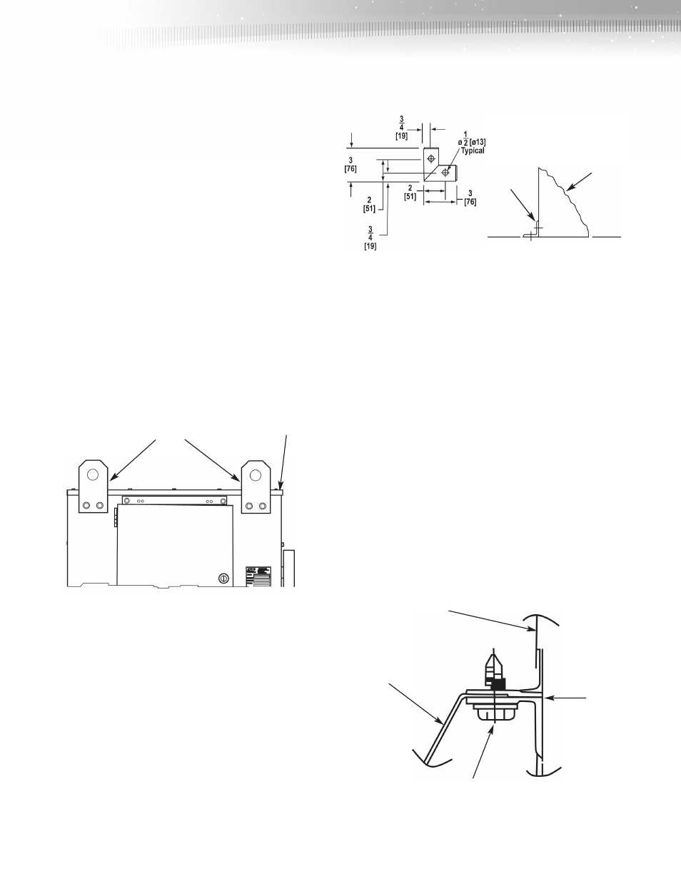
2.1 Anchoring
The AR ArrestAll collector is designed for installation on a
flat surface. Units must be suitably anchored. Anchor holes are
provided at the base of the support legs on the funnel bottom units
(Figure 2), and anchor clips are provided on the cart bottom
(Figure 3). Flat bottom units can be installed by drilling holes in the
bottom of the units. Holes drilled in the flat bottom base should be
gasketed or caulked to prevent air bypass.
Inlet Transitions
Standard accessories, such as the inlet transition (AR1 only), are
shipped loose for field installation with the caulk and attachment
hardware provided.
2.2 Field Assembly of Major Components
Funnel Bottom Units
Self-tapping screws and caulk are provided for installation of the
funnel bottom section to the cartridge section (Figure 4). Assemblies
can be bolted-up from the outside of the unit; interior access is not
required. See the field installation drawing for additional detail. The
fan is bolted to the top of the unit using the provided hardware. Fan
discharge orientation can be varied to suit owner ’s requirements.
See the fan installation drawing for additional detail.
Housing
Clips
Figure 3. Anchoring—Cart Bottom
Lifting Lugs
Typ (4) Places
Figure 1. Lifting Lugs
Top
Back
Front
Figure 2. Anchoring—Funnel Bottom
Cartridge
Section
Figure 4.
Caulk
Funnel
Section
Self Tappers