AAF International PRU User Manual
Page 7
7
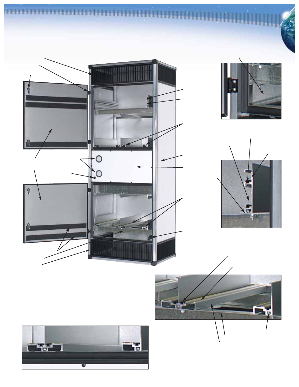
3.3 Typical RU Housing Details
A typical Recirculation Unit Model RU500 is shown.
Final filter track
2" After-filter track
Second stage HD
cassette positioning
and support track,
sealing face
Typical insulated
double wall panel
Fan section
Extruded
aluminum track
First stage HD
cassette positioning
and support track,
sealing face
2" Prefilter track
Outlet air grille
Door hinge
Door latch
Insulated double
wall access doors
Pressure gauges
Fan control
Filter side-seal gaskets
Track support
Inlet air grille
The RU is uniquely designed to accommodate and securely seal AAF’s
gas-phase chemical filter cassettes. Each housing incorporates AAF’s
patent-pending filter sealing system to ensure that the contaminated air
passes through the filter and does not by-pass around the filters. Typical
details of the tracks are shown in these illustrations. In some instances,
depending on the equipment supplied and the filters required, minor
track details may differ from those shown.
2" Prefilter track
Galvanized steel
(or similar) formed track
2" After-filter and final filter track. The final
filter track shown is designed to accept a
typical 1" nominal header-style filter.
Hollow core gasket
2" After-filter track
Final filter track
Cassette support track, sealing face
Hollow core face sealing gasket
Plastic strips provide low
friction cassette bearing surface
Track support hardware
Track support beam
Extruded aluminum track
Track connection detail at support beam. This detail shows AAF’s “quick release” track
installation method. Accurately located support post holes ensure high tolerance track
spacing. Note that the track connection is completely isolated from the filter sealing
surface and cannot interfere with filter installation.