5 | electrical connection, Y/yy – GEA Bock HG6 R134a User Manual
Page 13
D
GB
F
E
13
96181-01.2015-DGbFEI
5| Electrical connection
5 Electrical connection
DANGER! High voltage! Risk of electric shock! Only carry out work when the
electrical system is disconnected from the power supply!
INFO!
Connect the compressor motor in accordance with the circuit diagram
(see inside of terminal box).
Use suitable cable entry point of the correct protection type
(see name plate) for routing cables into the terminal box.
Insert the strain reliefs and prevent chafe marks on the cables.
Compare the voltage and frequency values with the data for the mains
power supply.
Only connect the motor if these values are the same.
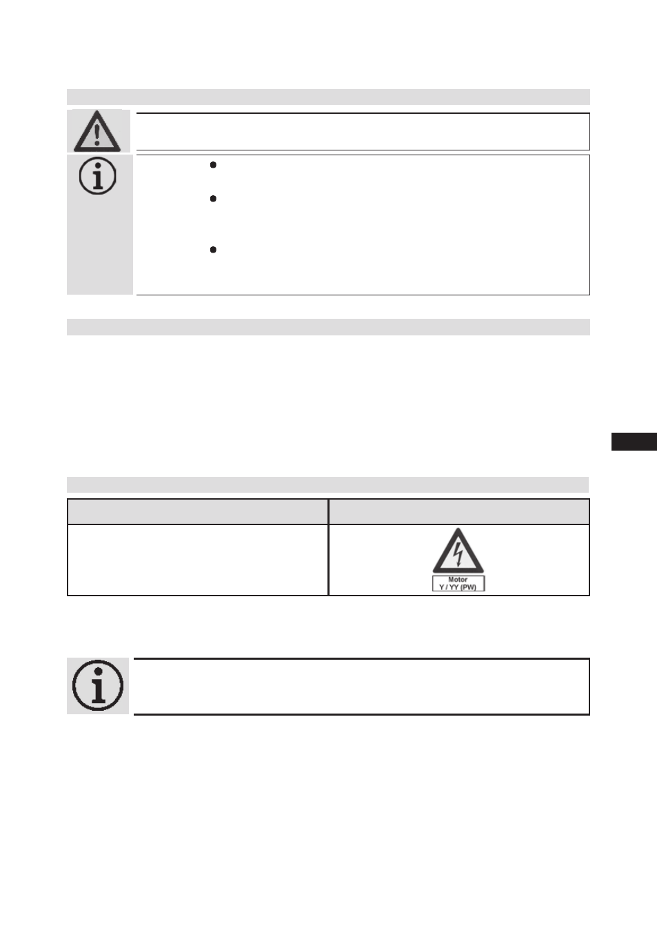
5.2 Standard motor, design for direct or partial winding start
Designation on the name plate
Sticker on the terminal box
Y/YY
Compressors with this marking are suitable for direct or partial winding start. The motor winding is
subdivided into two parts: Partial winding 1 = 66% and part winding 2 = 33%. This winding division
reduces the start-up current needed for a part winding start to approx. 65% of that for a direct start.
INFO!
A mechanical unloaded start with bypass solenoid valve is
not required.
5.1 Information for contactor and motor contactor selection
All protection devices and switching or monitoring units must be fitted in accordance with the local
safety regulations and established specifications (e.g. VDE) as well as with the manufacturer’s infor-
mation.
Motor protection switches are required! Motor contactors, feed lines, fuses and motor
protection switches must be rated on the basis of the maximum working current (see name plate).
For motor protection use a current-dependent and time-delayed overload protection device for moni-
toring all three phases. Set the overload protection device so that it must be actuated within 2 hours,
if there is 1.2 times the max. working current.