5 | electrical connection – GEA Bock HG34P User Manual
Page 13
D
GB
F
E
I
Ru
13
09618-11.2014-DGbFEIRu
5|
Electrical
connection
5 Electrical connection
DANGER! High voltage! Risk of electric shock! Only carry out work when the
electrical system is disconnected from the power supply!
INFO!
Connect the compressor motor in accordance with the circuit diagram
(see inside of terminal box).
Use suitable cable entry point of the correct protection type
(see name plate) for routing cables into the terminal box.
Insert the strain reliefs and prevent chafe marks on the cables.
Compare the voltage and frequency values with the data for the mains
power supply.
Only connect the motor if these values are the same.
5.1 Information for contactor and motor contactor selection
All protection devices and switching or monitoring units must be fitted in accordance with the local
safety regulations and established specifications (e.g. VDE) as well as with the manufacturer’s infor-
mation.
Motor protection switches are required! Motor contactors, feed lines, fuses and motor
protection switches must be rated on the basis of the maximum working current (see name plate).
For motor protection use a current-dependent and time-delayed overload protection device for moni-
toring all three phases. Set the overload protection device so that it must be actuated within 2 hours,
if there is 1.2 times the max. working current.
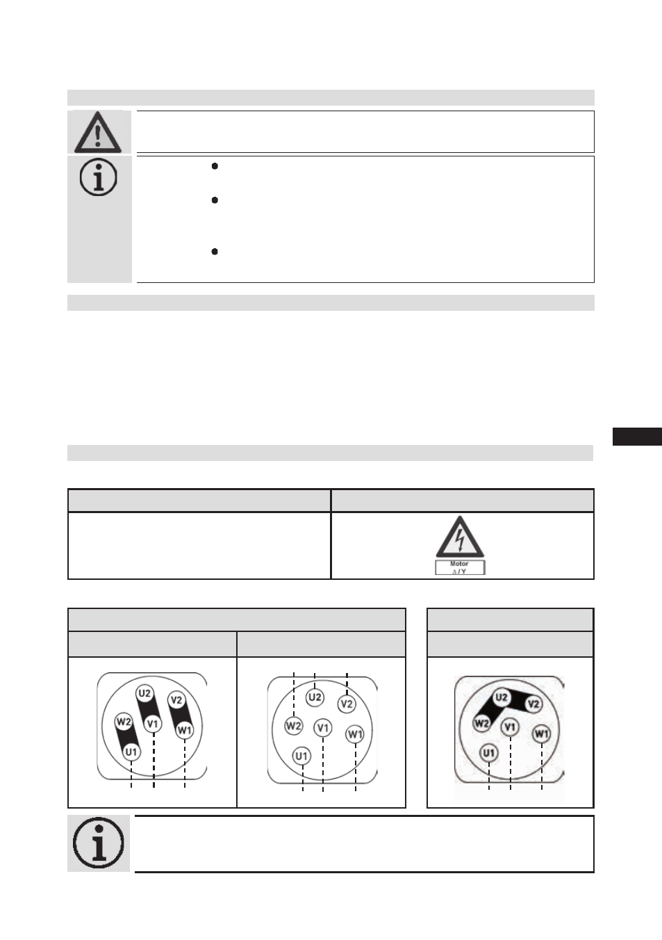
5.2 Connection of the driving motor
The compressor is designed with a motor for star-delta circuits.
Designation on the name plate
Sticker on the terminal box
∆ / Y
Star-delta start-up is only possible on 230 V voltage supply. Example:
230 V ∆
Direct start
Star-delta start
400 V Y
Direct start only
Elektrischer Anschluss
Electrical connection
Raccordement électrique
∆
/ Y
96027-11.06-DGbF
∆
Niedere Spannung
Low voltage
Bas voltage
Y
Hohe Spannung
High voltage
Haut voltage
L3
L1 L2
L3
L1 L2
Elektrischer Anschluss
Electrical connection
Raccordement électrique
∆
/ Y
96027-11.06-DGbF
∆
Niedere Spannung
Low voltage
Bas voltage
Y
Hohe Spannung
High voltage
Haut voltage
L3
L1 L2
L3
L1 L2
L1 L2
L3
L1 L2
L3
INFO!
The connection examples shown refer to the standard
version. In the case of special voltages, the instructions affixed to the
terminal box apply.