Thunderclap kit instructions v2 – Delptronics Thunderclap User Manual
Page 7
Thunderclap Kit Instructions V2
Page 7 of 11
Potentiometers
The potentiometers (pots) can either be soldered directly to the PCB, or they can be connected to the PCB via wires.
You can even do a combination where one or more pots are board-mounted and the others are connected with wires.
If you are building the Thunderclap into a panel, we recommend soldering all four pots directly to the circuit board.
That way, they will line up nicely (0.75 inches center-to-center) and the pots themselves will hold the PCB in place
without the need for a bracket of any kind.
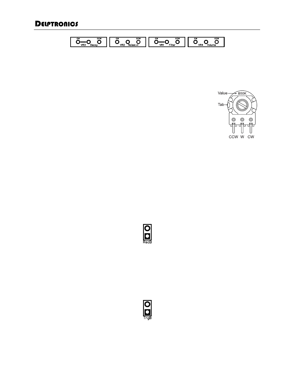
When viewed with the shaft pointing toward you, as in the picture to the right, the
pot’s value
is printed at the top. The pins are, from left to right, counterclockwise (anticlockwise), wiper,
and clockwise. The holes on the PCB are labeled CW and CCW to indicate which pin on the
pot gets connected to which hole on the PCB. If you are soldering one or more pots directly
to the PCB, the shafts will point away from the PCB.
There is a tab on the pots that must be removed or it will get in the way when you try to
mount them in the enclosure or panel. Hold the pot in one hand and grab the tab with a
small pair of pliers. Rotate the pliers away from the pot, and the tab will snap right off.
The marking on the PCB for the Filter and Decay pots have a line drawn from the wiper hole to the CW hole. This
indicates that the two pins are connected. You only need to connect a wire from the wiper pin from the pot to the
wiper hole on the PCB. You can connect the wiper pin to the CW pin with a small piece of wire on the pot itself, or
you can skip that connection entirely.
The pot values are as follows:
VR1 Filter
A1M
audio taper
VR2 Noise Lvl
B50K linear taper
VR3 Decay
B1M
linear taper
VR4 Volume
B20K linear taper
Record Button
In the Eurorack kit, the trigger and record buttons are the same. In the stompbox kit, the trigger button is the stomp
button and the record button is a pushbutton. The buttons are not polarized, so it does not matter which pin on the
button goes to which hole in the PCB.
Solder the wires to the button first, and then solder the other ends of the wires to the PCB. Check the style of the
record button. If the retaining nut goes on the inside of the enclosure, then the button must be inserted through the
hole in the enclosure before you solder the wires to the PCB.
Trigger Button
As stated above, in the Eurorack kit, the trigger and record buttons are the same. In the stompbox kit, the trigger
button is a stomp button. The stomp button has the retaining nut on the outside, so the order of soldering is not
critical.