Cub Cadet RZT 54 User Manual
Page 29
29
ADJUSTING THE GAUGE WHEELS AND ROLLERS
WARNING: Keep hands and feet away
from the discharge opening of the
cutting deck.
Model RZT50 Gauge Wheels
NOTE: The deck gauge wheels are an anti-scalp fea-
ture of the deck and are not designed to support the
weight of the cutting deck.
The mower deck cutting height can be set in any of
six height settings using the tractor’s deck lift handle.
The deck heights range from 1-1/2" to 4". For the
model RZT50, the deck gauge wheel position should
be approximately 1/4 to 1/2 inch above the ground
when the deck is set in the desired height setting.
Using the lift handle, set the deck in the desired
height setting, then check the gauge wheel distance
from the ground below. If necessary adjust as follows:
•
Visually check the distance between the front
gauge wheels and the ground. If the gauge
wheels are near or touching the ground, they
should be raised. If more than 1/2" above the
ground, they should be lowered.
•
Remove the lock nut securing one of the front
gauge wheel shoulder screws to the deck.
Remove the gauge wheel and shoulder screw.
See Figure 35.
•
Insert the shoulder screw into the one of four
index holes in the front gauge wheel bracket that
will give the gauge wheel a 1/4 to 1/2 inch
clearance with the ground.
•
Note the index hole of the just adjusted wheel,
and adjust the other gauge wheels into the
respective index holes of the other gauge wheel
brackets on the deck.
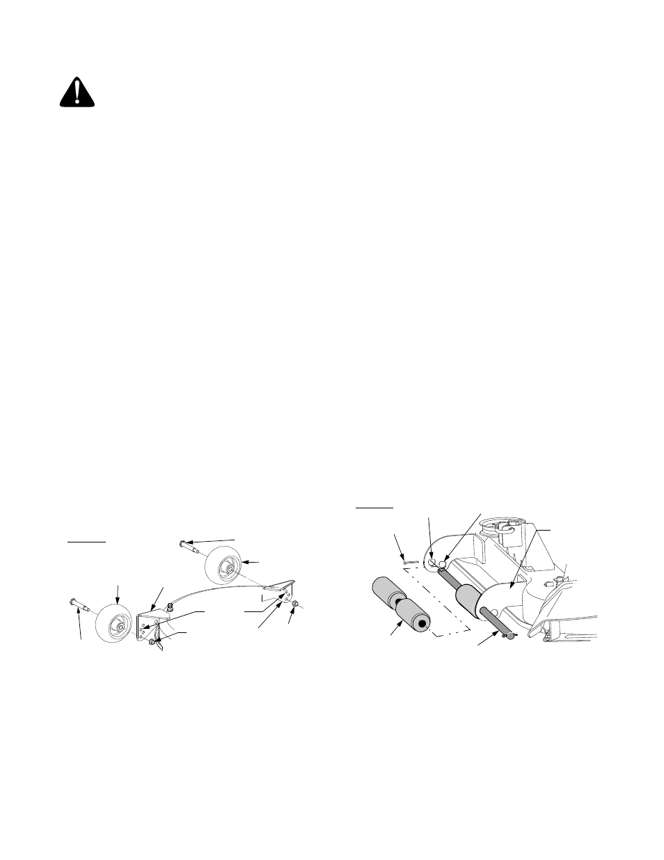
Figure 35
Model RZT54 Gauge Wheels and Rollers
The front gauge wheels on the RZT54 mower deck
are an anti-scalp feature, and should not ride on the
ground. The front gauge wheels should be approxi-
mately 1/4 to 1/2 inch above the ground when the
deck is set in the desired height setting.
The rear deck rollers can be set in either the low or
high position.
Using the lift handle, set the deck in the desired
height setting, then check the gauge wheel distance
from the ground below. If necessary adjust the front
gauge wheels as follows:
•
Visually check the distance between the front
gauge wheels and the ground. If the gauge
wheels are near or touching the ground, they
should be raised. If more than 1/2" above the
ground, they should be lowered.
•
Remove the lock nut securing one of the front
gauge wheel shoulder screws to the deck.
Remove the gauge wheel and shoulder screw.
Refer to Figure 35.
•
Insert the shoulder screw into the one of four
index holes in the front gauge wheel bracket that
will give the gauge wheel a 1/4 to 1/2 inch
clearance with the ground.
•
Note the index hole of the just adjusted wheel,
and adjust the other front gauge wheel into the
respective index hole of the other front gauge
wheel bracket.
The position on the rear deck rollers is generally not
changed. In the low position the rollers will roll the
grass. In the high position, the rollers are in a storage
position and do little or no rolling of the grass.
Change the roller position as follows:
•
Remove the cotter pin from the left end of the
roller shaft. See Figure 36.
•
Slide the roller shaft to the right and remove the
rollers as the shaft is fully withdrawn from the
right rear roller bracket. See Figure 36.
Figure 36
•
Insert the roller shaft through the other roller
bracket hole. Slide the rollers onto the shaft as
you slide the shaft to the left.
•
If necessary, rotate the roller shaft to align the flat
area on the left end of the shaft with the flat of the
hole in the left roller bracket. Slide the shaft
throught the left roller bracker and secure with the
cotter pin.
Shoulder
Screw
Front Gauge
Wheel
Gauge
Wheel
Bracket
Adjustment
Holes
Lock
Nut
Lock
Nut
Gauge
Wheel
Bracket
Index
Shoulder
Screw
Rear Gauge
Wheel
RZT 50
Low Position
High
Cotter
Roller
Roller Shaft
Pin
Right Rear
Roller Brkt.
RZT 54
Position