Leveling the deck, Seat – Cub Cadet 1222 User Manual
Page 15
15
Figure 8
•
If the gauge wheels have excessive clearance with
the surface below, lower the wheels to the index
hole that provides the approximate 1/2" clearance
as described above.
Refer to
Leveling the Deck
on page 15 of this manual for
more detailed instructions regarding various deck
adjustments.
Leveling the Deck
NOTE: Check the tractor’s tire pressure before
performing any deck leveling adjustments. Refer to
page 20 for information regarding tire pressure.
Front To Rear
The front of the cutting deck is supported by a stabilizer
bar that can adjusted to level the deck from front to rear.
The front of the deck should be between 1/4-inch and
3/8-inch lower than the rear of the deck. Adjust if
necessary as follows:
•
With the tractor parked on a firm, level surface,
place the deck lift lever in the top notch (highest
position) and rotate the blade nearest the discharge
chute so that it is parallel with the tractor.
•
Measure the distance from front of the blade tip to
the ground and rear of the blade tip to the ground.
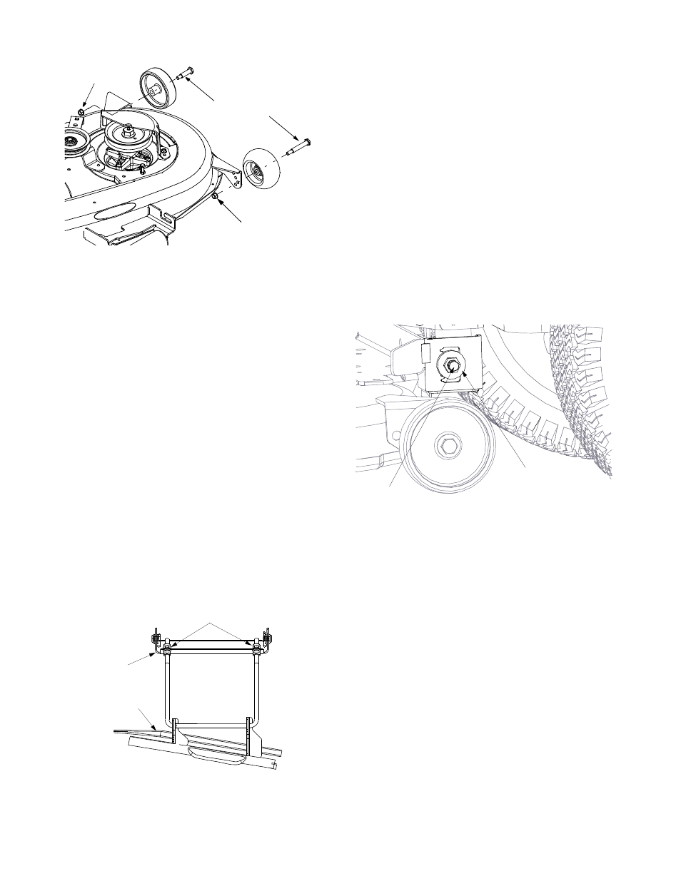
Figure 9
•
The first measurement taken should be between
1/4" and 3/8" less than the second measurement.
Determine the approximate distance necessary for
proper adjustment and proceed to the next step.
•
Locate the two lock nuts on the opposite side of the
stabilizer bracket. See Figure 9. Tighten the lock
nuts to raise the front of the deck; loosen the lock
nuts to lower the front of the deck
Side to Side
If the cutting deck appears to be mowing unevenly, a
side to side adjustment can be performed. Adjust if
necessary as follows:
•
With the tractor parked on a firm, level surface,
place the deck lift lever in the top notch (highest
position) and rotate both blades so that they are
perpendicular with the tractor.
•
Measure the distance from the outside of the left
blade tip to the ground and the distance from the
outside of the right blade tip to the ground. Both
measurements taken should be equal. If they’re
not, proceed to the next step.
Figure 10
•
Loosen, but do not remove, the hex cap screw on
the left deck hanger bracket. See Figure 10.
•
Balance the deck by using a wrench to turn the
adjustment gear (found immediately behind the hex
cap screw just loosened) clockwise/up or
counterclockwise/down.
•
The deck is properly balanced when both blade tip
measurements, taken earlier, are equal.
•
Retighten hex cap screw on the left deck hanger
bracket when proper adjustment is achieved.
Seat
•
Move the seat adjustment lever (located under the
seat) to the left and slide the seat forward or
backward. Once the desired position is reached,
release the lever and the seat should lock into one
of the six adjustment positions.
IMPORTANT:
The seat must be engaged in the seat stop
for operating the tractor. Stand behind the machine and
pull back on seat until fully engaged into stop.
Lock Nut
Shoulder Screws
Lock Nut
Deck
Stabilizer
Bracket
Deck
Lock Nut
Hex Cap
Adjustment
Gear
Screw