4 x 2 gear selector – Cub Cadet 4 x 2 Big Country - Steel Bed User Manual
Page 21
4 X 2 Gear Selector
17
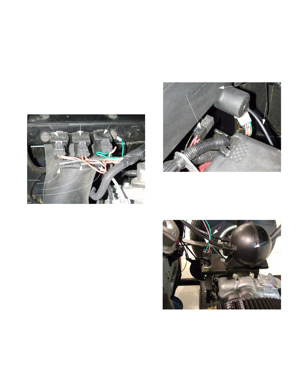
1.10. The vacuum line marked with a blue dot pro-
vides vacuum to the actuator that controls
the differential lock. The differential lock is
engaged by a separate vacuum actuator. The
differential lock is disengaged by spring action
when two conditions are met: (1) The differential
lock solenoid is not activated and (2) If the differ-
ential lock was previously engaged, the speed of
the rear wheels is equal. The vacuum line with
the blue dot should connect to the inner sole-
noid. The inner (differential lock) solenoid has
one yellow wire with a white trace and one
green wire. See Figure 1.10.
1.11. Solenoid operation is as follows:
•
A vacuum manifold connected to the vacuum
reservoir connects to the lower fitting on all three
solenoids.
•
The color-marked elbows connect to the upper
fitting on each solenoid. The vacuum lines that
are connected to each solenoid by a color-
marked elbow lead from the solenoid to an actu-
ator.
•
The orange and white wire provides power to the
forward and reverse solenoids. It should be
“hot” whenever the key switch is on. The sole-
noids are controlled by the presence or lack of
ground at the other wire that connects to each.
•
The differential lock solenoid has a constant
ground, provided by the green wire. Presence of
current at the yellow and white wire triggers the
differential lock solenoid.
•
When energized, each solenoid will connect
vacuum from the manifold (reservoir), through
the color marked elbow, to its actuator.
Figure 1.10
Dots:
red
green
blue
Forward Reverse Differential
solenoid lock solenoid
•
When the solenoid is de-energized, it provides a
vent to the atmosphere to release the pull on the
diaphragm.
NOTE: Because the differential lock actuator
only pulls in one direction, the vent from the
actuator is located in the plenum.
See Figure 1.11.
1.12. The vacuum reservoir (accumulator) holds a
reserve supply of vacuum to operate the actua-
tor in low engine vacuum conditions. It is
mounted to the top of the transaxle.
See Figure 1.12.
NOTE: One vacuum line connects the intake
manifold to the vacuum reservoir. The other vac-
uum line connects the vacuum reservoir to the
solenoids.
Figure 1.11
Plenum
Starter relay
Vent tube for
differential
lock actuator
Figure 1.12
Vacuum (to solenoids)
Vacuum
reservoir
Vacuum
(from intake manifold)